

8 Pin Timer Relay Wiring Diagram
Understand 8-pin timer relay wiring with easy diagrams. Learn pinout, connection steps, and functions. Perfect for electricians and electronics hobbyists.

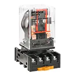
8 pin relay light automation
The 8-pin timer relay is a commonly applied mechanism that is used to apply automation within circuits by intervals of time. It operates by holding up switching of its contacts according to predetermined time. Lighting, motors, or any device that has a programmable delay can be controlled by the relay with wires connected to the input voltage on the coil side between the coil terminals and to the output (NO or NC) terminals to the load positions. This confers on it a vital role in automation, control panels, and DIY electronics.
Relay Function Logic:
| Pin No | Function | Connection |
|---|---|---|
| 2 & 7 | Coil (AC/DC Supply) | Connect to Power Input |
| 1 & 8 | Common (COM) | Relay Switching Terminals |
| 3 & 6 | Normally Open (NO) | Output when timer completes |
| 4 & 5 | Normally Closed (NC) | Output until timer ends |
| Knob/DIP | Time Adjustment | Set desired delay (e.g., 5s) |
8 pin timer relay connection
The 8-pin timer relay is a general-purpose time delay relay used on automation, control panels, and industrial timing controls. Knowledge of its pinout and wiring assists in adjusting on-delay, off-delay or cyclic applications. It is standard that an 8-pin relay would consist of input voltage and normally open (NO) and normally closed (NC) contacts as well as control coils.
The way you need to wire it is something like this: coil (pins 2 and 7), common (pins 8 and 1), and NO/NC contacts (keep it 3, 4, 5, and 6 depending on the model you have). The timer switches the output on, after a given delay, after being powered. This enables it to be applicable in motor control, lighting, and sequential activities.
timer relay wiring for beginners
| Timer Model | Voltage | Delay Type | Timing Range |
|---|---|---|---|
| H3Y-2 | 12V DC | On-Delay | 0-10s |
| AH3-3 | 220V AC | Off-Delay | 0-60s |
| S1DX-M1C | 24V DC | Repeat Cycle | 1s - 30min |
Frequently Asked Questions - 8 Pin Timer Relay Wiring Diagram:
What is an 8 pin timer relay?
A relay with 8 terminals used to control time-based electrical switching in automation systems.
How do I wire an 8 pin timer relay?
Connect coil to pins 2 & 7, common to pins 1 & 8, NO to 3 & 6, and NC to 4 & 5.
What voltage is required for the timer relay coil?
Depends on model; typically 12V DC, 24V DC, or 220V AC.
What does NO and NC mean in timer relay?
NO means Normally Open (closes after time), NC means Normally Closed (opens after time).
Can I use an 8 pin relay for delay ON function?
Yes, most 8-pin relays support delay ON and other timing modes.
Is a timer relay the same as a normal relay?
No, timer relays include timing control circuits, unlike regular relays.
Where is the timing knob located?
Typically on the front of the relay body, marked with time settings.
Can I use this relay for AC and DC circuits?
Yes, depending on the model and coil voltage rating.
How to test if the timer relay is working?
Apply voltage to the coil and observe delay in switching at the NO/NC contacts.
What are common applications of 8-pin timer relays?
Used in motor controls, lighting automation, industrial machinery, and HVAC systems.
Related Posts
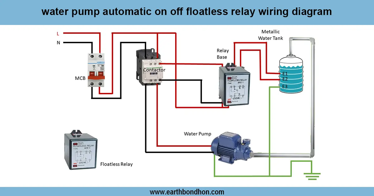
Automatic water level controller wiring
Clear wiring diagram and guide for water pump automatic ON/OFF using a floatless relay, ensuring reliable pump control without mechanical floats.
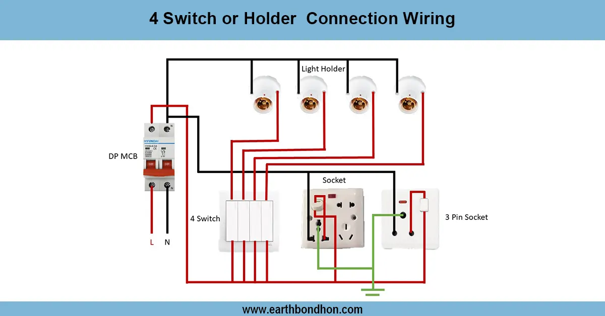
4 Switch Holder Connection Wiring
Learn how to wire four switches to four separate lamp holders for independent control in any room. Step‑by‑step guide with safety tips and cable size recommendations.

Manual Light sensor connection for street light
Wiring diagram for 3-phase electric systems using light sensors to automate lighting control, improving energy efficiency and safety in industrial and commercial setups.
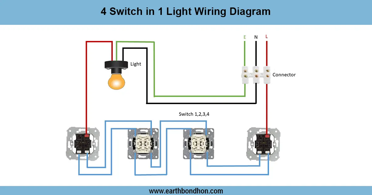
4 Switch 1 Light Control Wiring
A wiring diagram showing how to control one light using four different switches from different locations. Ideal for staircases or long corridors.

Voltage monitor Relay connection
Learn how to wire a voltage monitor relay in a DOL starter to protect 3-phase motors from phase loss, phase reversal, and voltage faults with easy connection steps.

3 Phase SPD Connection
Detailed 3 phase SPD connection diagram showing how to wire surge protection devices to safeguard electrical systems from transient overvoltages.