

Doorbell Wiring Diagram
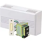
Wiring diagram for connecting a doorbell system to 4 rooms. Learn how to use push buttons, bells, and transformers for clear alerts in multiple rooms.

Corridor light circuit diagram
The wiring system that contains 4 rooms and a single switchboard is capable of turning off the alerts in one specific elucidation of the doorbell with bells or buzzers in different rooms. This kind of system can be applied at homes, clinics, or offices to be used where there is a need to notify various occupants one by one. The wiring diagram illustrates the connection of push buttons to buzzers or bells in four rooms to be powered by a transformer. This is a wiring solution that is simple, effective, and easy to maintain, and everybody is notified in the right place without the intricate intercom systems.
Basic Formula for Load Calculation:
Total Load (W) = Voltage (V) × Current (A)
Example: If each doorbell uses 12V and draws 0.2A, then for 4 rooms:
Total Load = 12V × 0.2A × 4 = 9.6 Watts
Key Components in Table Format
| Component | Quantity | Purpose |
|---|---|---|
| Push Button | 4 | Trigger bell in each room |
| Door Bell | 4 | One per room |
| Transformer | 1 | 12V or 24V supply |
| Selector Switch | Optional | To choose which room to ring |
| Wire (Low Volt) | As needed | Connects components |
corridor hallway wiring connection
The 4-room doorbell wiring diagram assists in the installation of a single-bell system with a variety of buttons in order to notify particular rooms. This is a very good system when it comes to houses, small offices, or clinics. The push button can be dedicated to a single room or wired in a common circuit with a selector switch. The diagram usually encompasses a 12V/24V transformer, doorbells (either buzzers or chimes), and wire conduits. The system is charged with a centralized transformer, and the bell in the concerned room rings when we press a push button. This form of multi-room setup is affordable, and the communication or notification is timely. This should be done through proper low-voltage wire and a secure mode of installation.
2 way switch corridor lights wiring diagram
| Room No. | Button ID | Bell Status | Wire Length (approx) | Remarks |
|---|---|---|---|---|
| Room 1 | B1 | Ringing | 12 ft | Working |
| Room 2 | B2 | Silent | 15 ft | Button not pressed |
| Room 3 | B3 | Ringing | 18 ft | Active Circuit |
| Room 4 | B4 | Silent | 20 ft | Standby |
Frequently Asked Questions - Doorbell Wiring Diagram:
What is a 4-room doorbell system?
It allows separate doorbells to ring in four different rooms using individual buttons and a centralized power supply.
Can I use one transformer for all 4 bells?
Yes, a single transformer with appropriate power can run multiple bells if wired correctly.
Do I need a separate wire for each room?
Yes, ideally each room should have its own line from the switch or selector unit.
What voltage should I use for the bell system?
Most doorbells use 12V to 24V AC or DC, depending on the bell and transformer.
Can I add an intercom to this system?
Yes, intercom units can be added in parallel but require separate wiring.
Is it safe to DIY the bell wiring?
Yes, if you're working with low voltage and follow proper safety standards.
How to wire a 4-room doorbell selectively?
Use push buttons that connect to each bell in series or via selector switches.
Can I use wireless bell units instead?
Yes, wireless multi-room bells exist but require power or batteries.
Does the bell need a relay?
For high loads or central control, a relay may be used.
Where should the transformer be placed?
Near the power source or distribution box, not in moist areas.
Related Posts
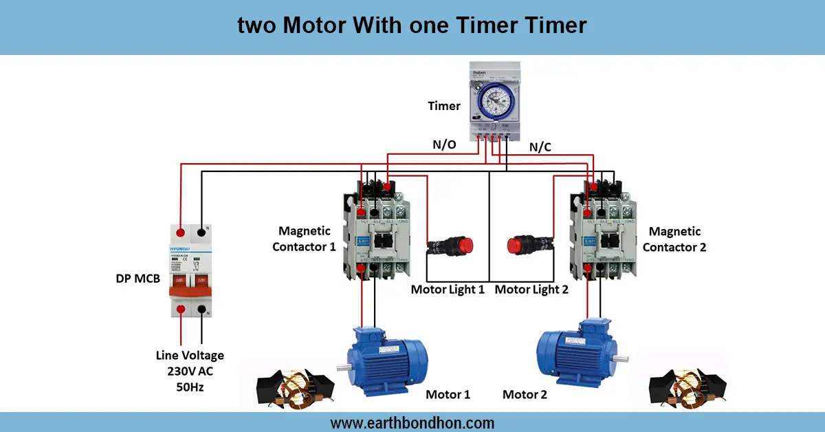
Motor with on delay Timer
Wiring diagram for controlling two motors with a single timer to automate motor operation in industrial, agricultural, or manufacturing applications.
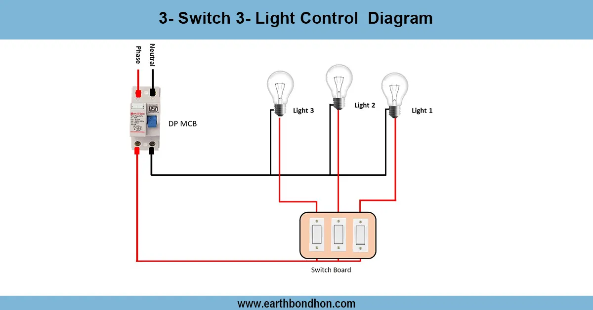
3 Bulbs And 3 Switches Diagram
Learn how to wire 3 lights with 3 individual switches. Easy step-by-step diagram, formula summary, and connection table for beginners and professionals.
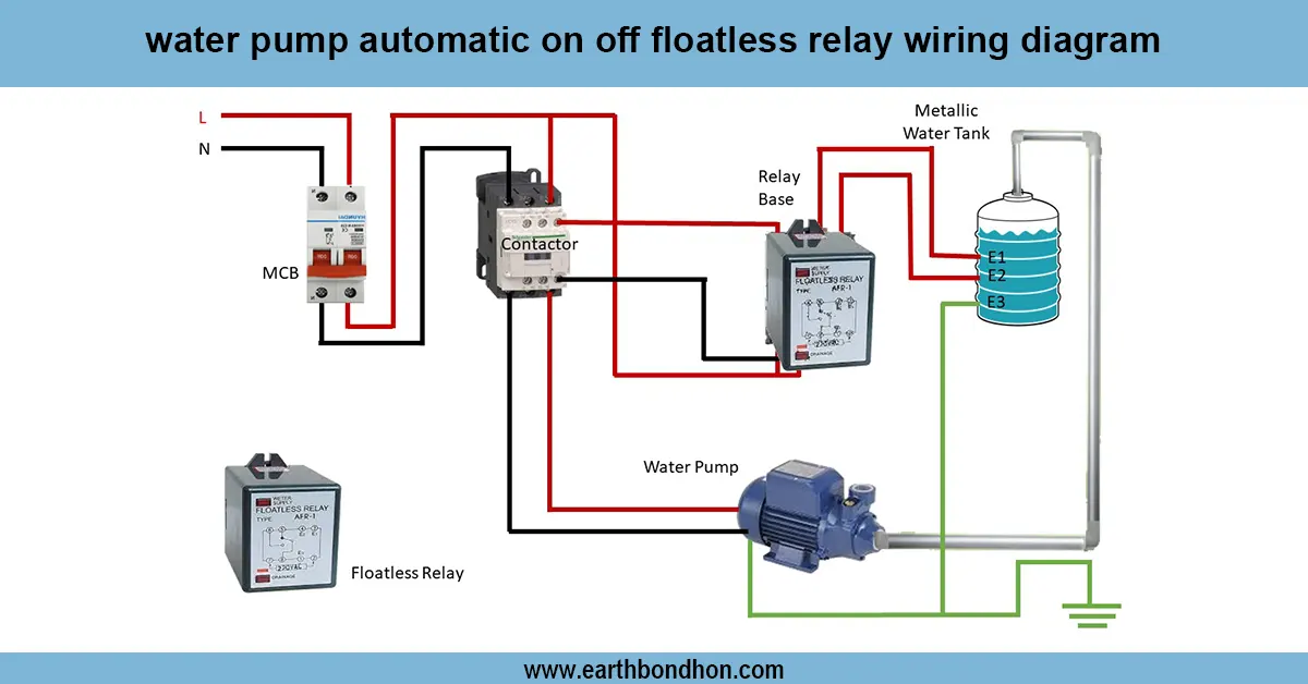
Automatic water level controller wiring
Clear wiring diagram and guide for water pump automatic ON/OFF using a floatless relay, ensuring reliable pump control without mechanical floats.

Parallel Circuit with 3 bulbs
Understand how to wire a parallel circuit with three light bulbs. Learn the diagram, current flow, voltage sharing, and total resistance with practical wiring tips.
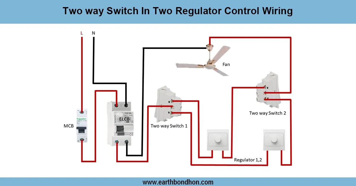
Two way switch fan regulator connection
Wiring diagram for controlling two separate light regulators from two locations using two-way switches for flexible ON/OFF control.
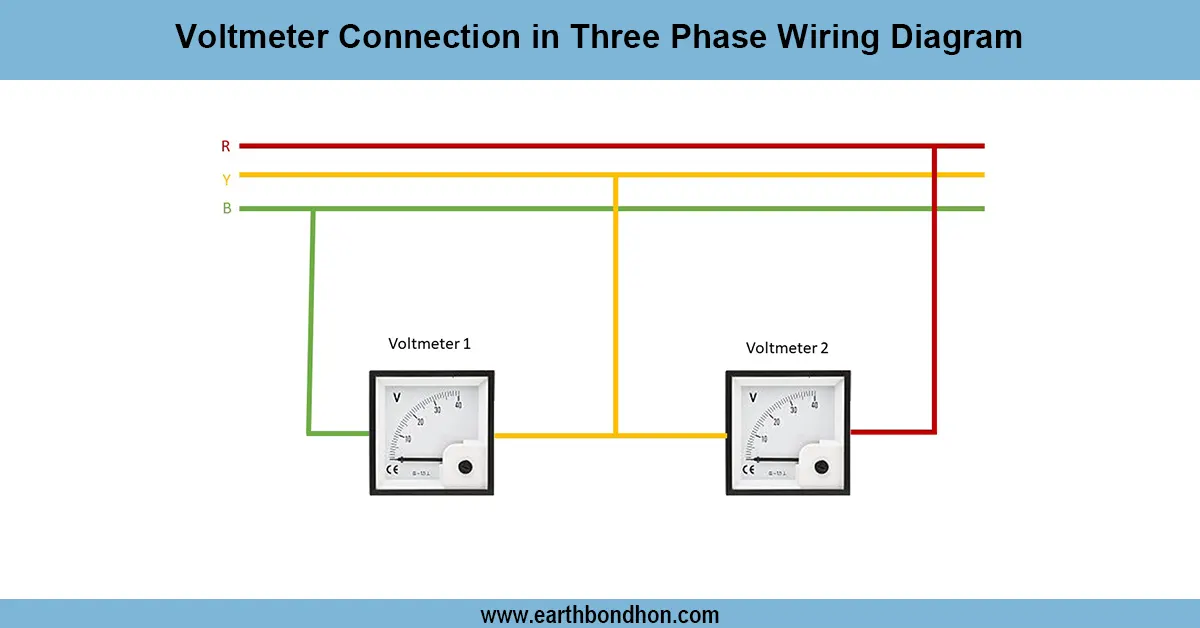
Three phase voltmeter connection
volts times the square root of 3, which happens to be rounded off to 1.732. For 2 lines each carrying 120 volts, the calculation for this is 120 volts times 1.732, and the result is rounded up to 208 volts.