


Corridor Wiring Circuit Diagram
Learn how to wire a corridor lighting system using switches at both ends. Ideal for homes, offices, and hotels to control lights from multiple points.

corridor wiring diagram
The operation of a single light fixture but two or more remote locations, that is, on-off and intermediate switch operation of a single light fixture, is demonstrated in a corridor wiring circuit diagram. Such an arrangement is particularly convenient when there is a long corridor or a staircase because one can switch on the light at both ends. Wiring two switch positions at the point of entry and exit of the corridor with an intermediate position in the middle (in case they are needed) allows them to toggle the light no matter where they are. The approach will make the lighting zones more accessible, safe, and energy-efficient when multi-access lighting is involved.
Wiring Formula:
Corridor Light = 2-Way Switch + (Optional) Intermediate Switch + Load
Component Summary Table
| Component | Symbol | Function |
|---|---|---|
| 2-Way Switch | S1, S2 | Control from 2 locations |
| Intermediate Switch | S3 | Optional for more than 2 switches |
| Light | L | Load controlled |
corridor switch wiring
A corridor wiring system is a very effective way of mastering a single light at two or more access points or stations, and it is generally applied in long corridors, stairs, and large rooms. Such a system meets the requirements of convenience and energy saving because the users are able to switch off or switch on lights at one end of the corridor or the other. The regular setup is 2-way or intermediate switches, depending on the control points. It is an absolute layout in a residential and commercial place, such as a hotel and an office, where it is required to control lighting in various access points. Being familiar with this wiring can aid anytime anyone would like to do some DIY electrical skills or troubleshooting/implementation of corridor lighting.
corridor light wiring system
| Switch 1 | Switch 2 | Light Status |
|---|---|---|
| Up | Up | ON |
| Up | Down | OFF |
| Down | Up | OFF |
| Down | Down | ON |
Frequently Asked Questions - Corridor Wiring Circuit Diagram:
What is a corridor wiring diagram?
It shows how to control one light from two or more switches.
Which switches are used in corridor wiring?
Two-way and intermediate switches are used.
Can I use only two switches in a corridor?
Yes, two-way switches allow control from two locations.
Where is corridor wiring used?
Common in hallways, staircases, and hotels.
What is the function of an intermediate switch?
It allows control from three or more points.
Is neutral wire needed in switch loop?
Not always; depends on the wiring method.
Can corridor lights be automated?
Yes, using motion sensors or smart switches.
How do I test corridor wiring?
Toggle switches and check if light turns on/off.
Is this setup safe for residential use?
Yes, if installed with proper standards.
Can LED lights be used in corridor circuits?
Absolutely, just ensure switch compatibility.
Related Posts
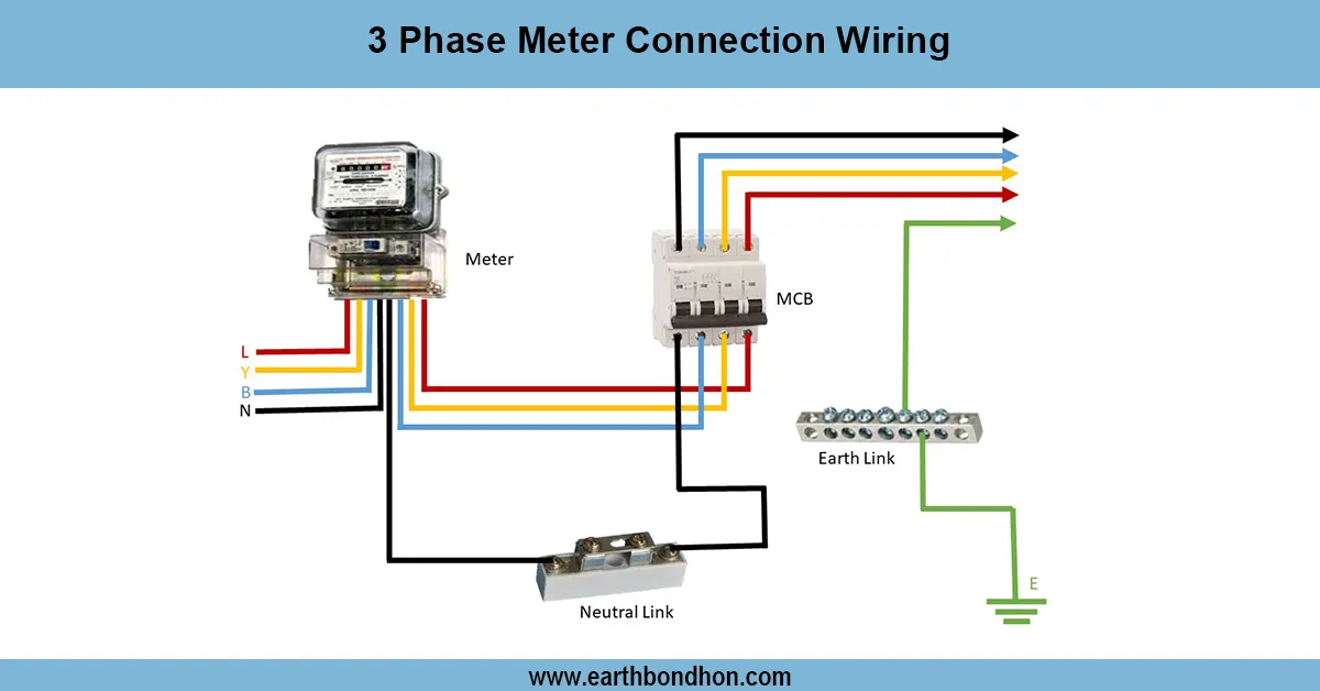
3 Phase Meter Connection Diagram
Learn the correct wiring connection for a 3-phase meter with step-by-step guidance, ensuring safe and accurate power measurement for 3-phase electrical systems.
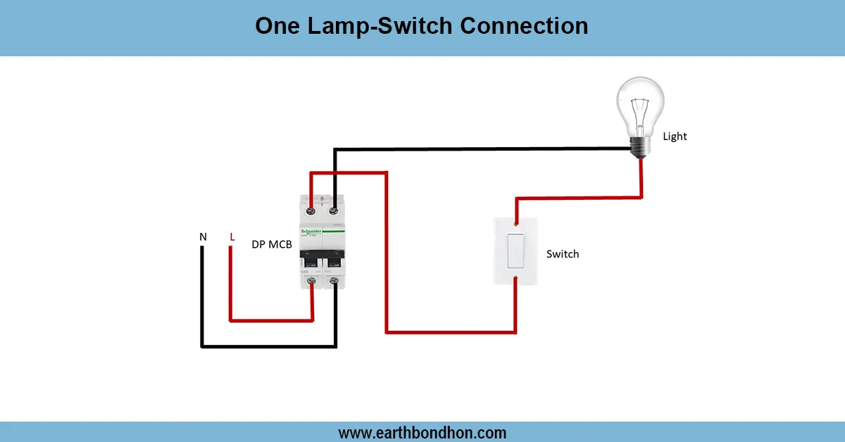
1 Way light Switch wiring Diagram
Learn how to wire a 1-way light switch to control a single light. Ideal for rooms, corridors, and small areas where one switch operates one light.
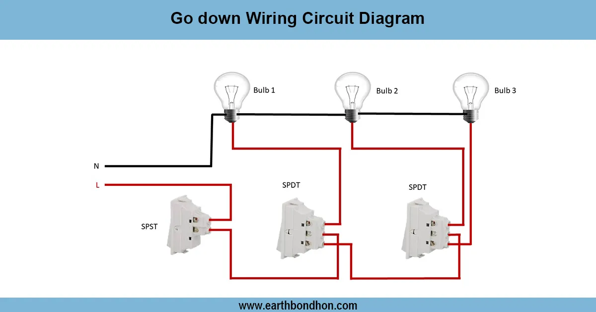
Go down Wiring Circuit Diagram
Learn the Go Down wiring circuit diagram with clear steps for safe, efficient electrical wiring. Perfect for warehouses and storage areas.
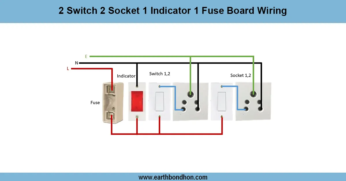
Switch and Socket Connection Diagram
Understand switch and socket connection diagrams for safe and efficient home wiring. Step-by-step wiring guide for switches and electrical sockets.
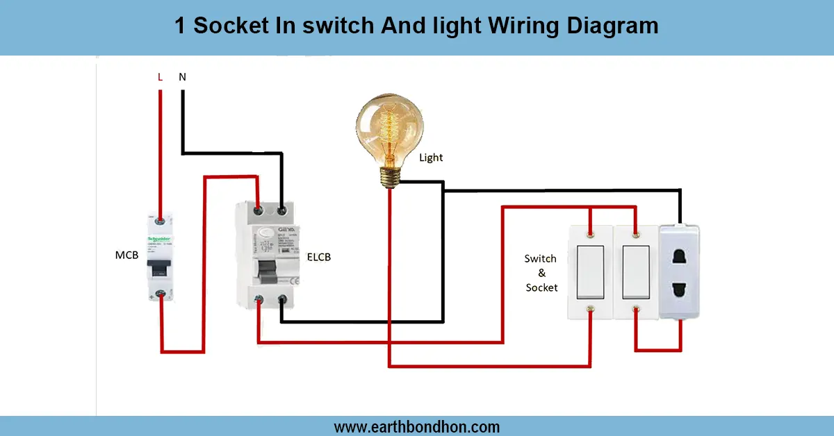
1 Switch 1 Socket connection
Learn how to wire a light and socket using one switch. Simple connection for homes and offices with a clear circuit diagram and safety instructions.
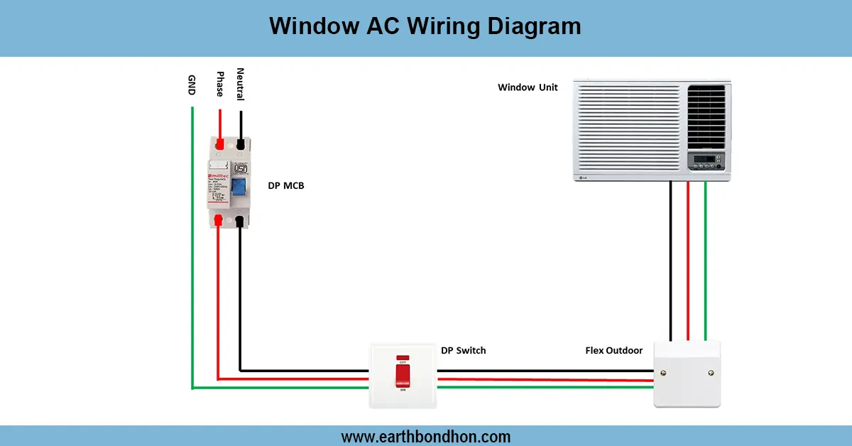
Window AC wiring
Detailed wiring diagram for window AC units covering power connections, thermostat wiring, compressor, fan motor, and safety components for safe operation.