


Motor control from two places
Wiring diagram for using two-way switches to control a motor’s ON/OFF operation from two different locations safely and efficiently.

two way switch motor wiring
Wiring two way switches in motor circuits enables the motor to operate ON or OFF under two locations with traveling wires between switches that feed the motor switch.
Formula & Table Summary:
Components: Two SPDT switches, motor, power supply (live, neutral, ground), traveler wires.
Connections: Live supply connects to common terminal of Switch 1; traveler wires connect Switch 1 and Switch 2; Switch 2 common terminal connects to motor supply.
Operation: Toggling either switch changes the motor supply state (ON/OFF).
Safety: Ensure proper grounding and use circuit protection devices.
| Terminal | Connection | Function |
|---|---|---|
| Switch 1 Common (C1) | Connects to Live supply | Power input |
| Switch 1 Travelers (T1, T2) | Connect to Switch 2 travelers | Switching paths |
| Switch 2 Common (C2) | Connects to Motor Live input | Power output |
| Motor Neutral | Connects to Neutral line | Completes circuit |
| Earth (Ground) | Connects to Motor Frame | Safety grounding |
two way switch installation motor
The method of wiring the motor, where two way switch is used, allows using two different locations to start and stop the motor. It comes in particular handy on motors which are located somewhere such as a workshop or on a conveyor system where there is a requirement to be able to turn the motor ON and OFF conveniently at various locations. This wiring has two SPDT switches in either 3 or 4 wire buss which are connected as traveler wires to complete the supply line to the motor starter or direct motor load. The motor is used with a distribution of neutral and ground wires to be safe. Such arrangement makes motor control less complicated and does not require complex relays or timers and improves user convenience and safety of operation.
electrical motor two way switch
| Switch 1 Position | Switch 2 Position | Motor Status |
|---|---|---|
| Up | Up | OFF |
| Up | Down | ON |
| Down | Up | ON |
| Down | Down | OFF |
Frequently Asked Questions - Motor control from two places:
What is a two way switch in motor wiring?
A setup allowing motor ON/OFF control from two locations using two SPDT switches.
How many traveler wires connect the two switches?
Two traveler wires connect the switches for power switching.
Can this control motor speed?
No, this controls only ON/OFF operation.
Is grounding necessary?
Yes, for safety and to protect against electric shock.
Where is the live wire connected?
To the common terminal of the first switch.
What happens when either switch toggles?
The motor turns ON or OFF regardless of the other switch position.
Can I use this wiring for any motor?
Generally yes, but check motor voltage and current ratings.
Is neutral connected to the switches?
No, neutral connects directly to motor neutral terminal.
Do I need circuit protection?
Yes, use proper breakers or fuses for motor protection.
Can I install this myself?
Only if experienced with electrical wiring and safety.
Related Posts
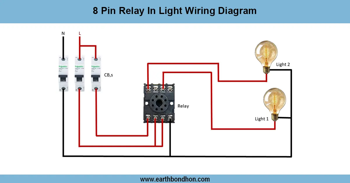
8 Pin Relay In Light Wiring Diagram
Understand how to wire an 8-pin relay for controlling lights using a switch or sensor. Ideal for automation, safety, and efficient lighting systems.
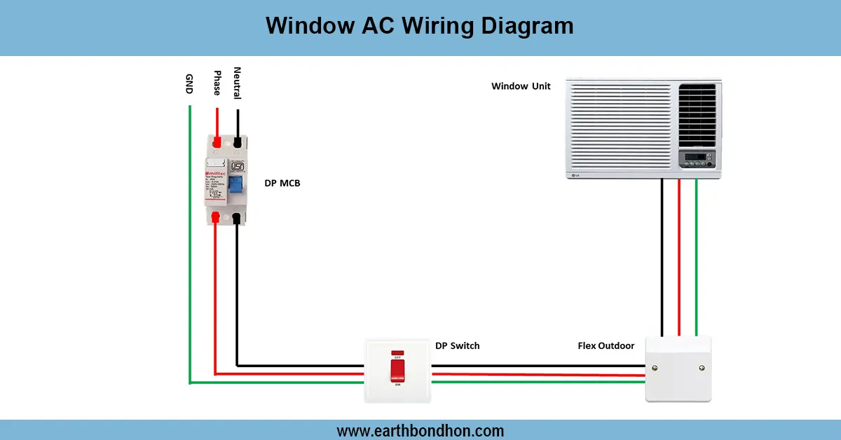
Window AC wiring
Detailed wiring diagram for window AC units covering power connections, thermostat wiring, compressor, fan motor, and safety components for safe operation.
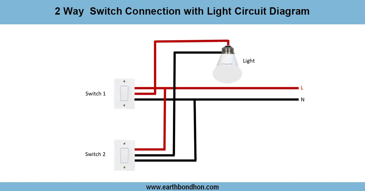
2 Way Switch Wiring
Learn how to wire a 2-way switch to control lights from two locations. Use our guide and wiring diagram for clear, safe, and simple electrical connections
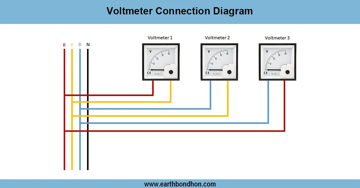
Voltmeter connection circuit diagram
Voltmeters are connected in parallel with whatever device's voltage is to be measured. A parallel connection is used because objects in parallel experience the same potential difference.
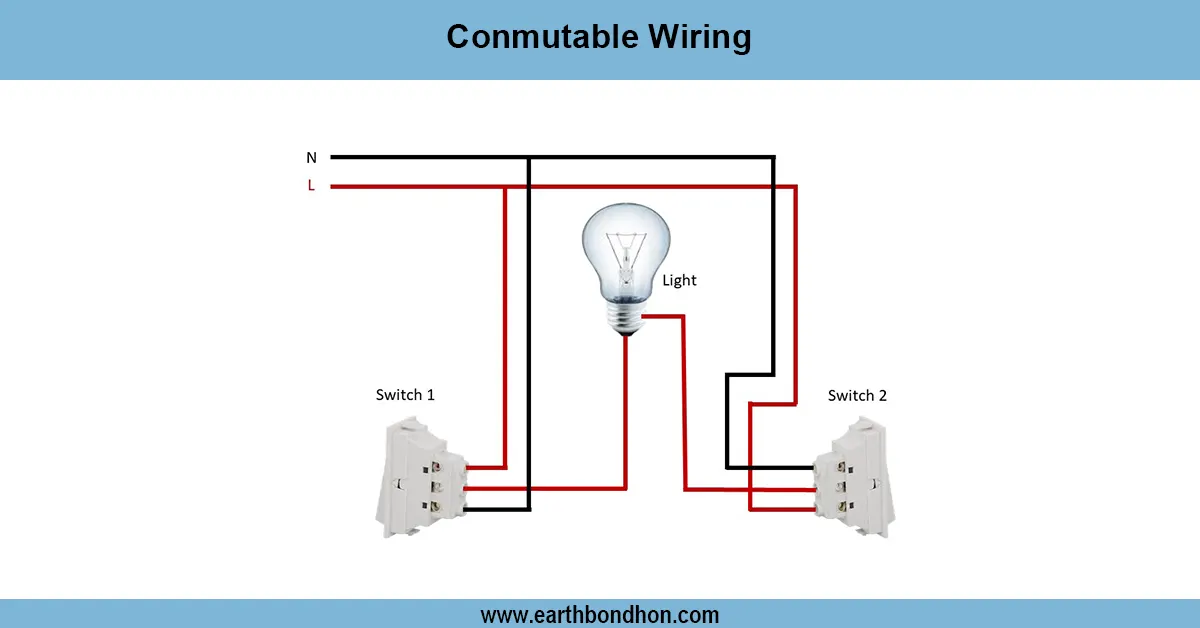
Commutable light Wiring Diagram
Conmutable wiring allows controlling a single light from two switches, ideal for staircases or hallways, using two-way (SPDT) switches for convenience and safety.
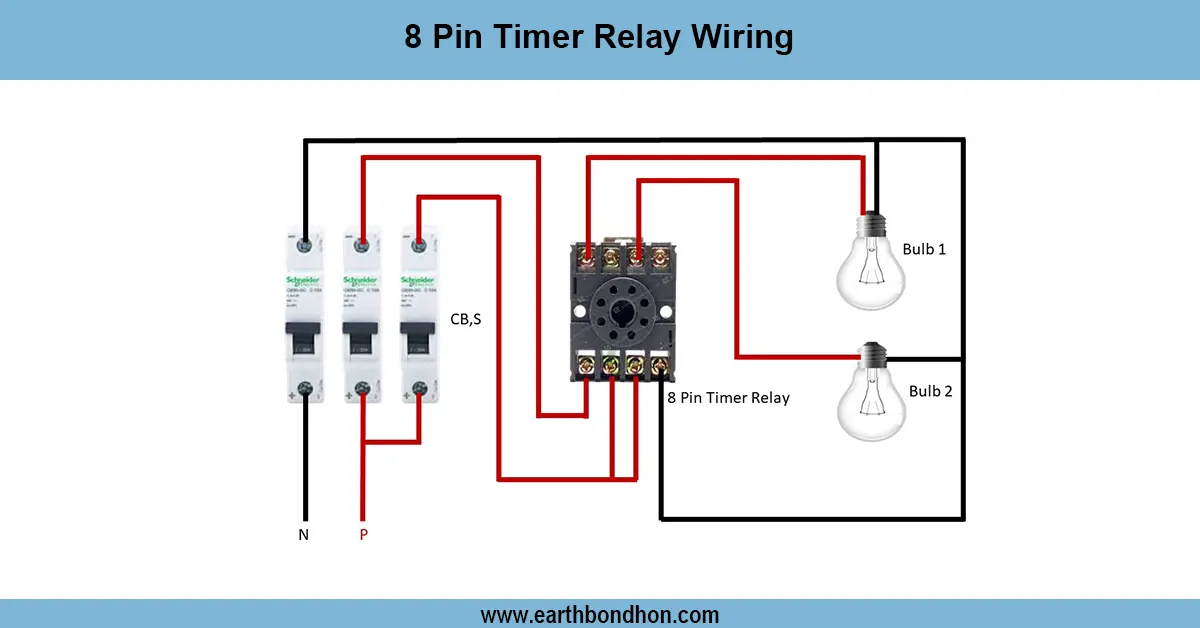
8 Pin Timer Relay Wiring Diagram
Understand 8-pin timer relay wiring with easy diagrams. Learn pinout, connection steps, and functions. Perfect for electricians and electronics hobbyists.