


Commutable light Wiring Diagram
Conmutable wiring allows controlling a single light from two switches, ideal for staircases or hallways, using two-way (SPDT) switches for convenience and safety.

SPDT switch light control
With commutable wiring, it is possible to control a light by two or more controls, i.e., two-way or intermediate switches. This arrangement proves particularly beneficial in such areas as corridors, stairways, and long hallways. It enhances availability, security, and ease. This guide contains circuit diagrams, simple formulas, and an inventory of parts used in establishing commutable wiring in a residential or commercial building.
Wiring Summary:
- Use 2x Two-Way Switches for Dual Point Control
- Connect L (Live) wire to the first switch common terminal
- Two traveler wires connect both switches' L1 & L2
- Output from second switch's common goes to light
- Neutral directly connects from distribution to bulb
Conmutable circuit explanation
Commutable wiring is where all wiring can be switched by two or more switches to operate one point of light. This is mostly applied in staircases and in corridors or in big rooms where there are more than one entrance points. It also enables users to switch on or switch off lights at different places conveniently. The simple one would be employing SPDT (two-way) switches and proper wiring in between the switches. The wiring diagram will vary depending on the installation (2-way or 3-way), and the aim will be the same: to provide the user convenience and to save energy.
conmutable wiring diagram
| Component | Quantity | Description |
|---|---|---|
| Two-Way Switch | 2 | Controls light from 2 locations |
| Electrical Wire | As per layout | For L, N, and traveler connections |
| Light Bulb | 1 | Connected to switch output |
Frequently Asked Questions - Commutable light Wiring Diagram:
What is conmutable wiring?
It allows a light to be controlled from two or more switches using two-way or intermediate switches.
Where is conmutable wiring used?
Commonly used in stairways, corridors, or large rooms with multiple entrances.
Which switch is used in conmutable wiring?
Two-way (SPDT) switches are used, and sometimes intermediate switches for 3-point control.
How does a two-way switch work?
It redirects the circuit between two traveler wires, enabling ON/OFF from different locations.
Is conmutable wiring safe?
Yes, when done correctly with proper insulation and earthing.
Can I control a fan with conmutable wiring?
Technically yes, but usually it is used for lighting control.
How many switches can I use in conmutable wiring?
Up to 3 or more using intermediate switches between two-way switches.
What wire is needed for conmutable wiring?
Typically 1.5mm² copper wire for lighting circuits.
What are traveler wires?
Wires connecting terminals between the two switches in the setup.
Do I need an electrician for this setup?
It's recommended unless you're confident with safe electrical practices.
Related Posts

8 Pin timer Relay wiring
Learn the pin configuration and wiring method for an 8‑pin timer relay to control loads with delay. Includes coil connections, NO/NC contacts, and timing logic.
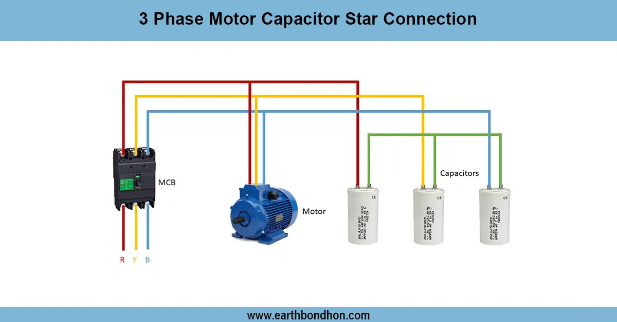
3 Phase Motor Star Connection Diagram
Learn 3-phase motor capacitor star connection wiring for starting and running capacitors, ensuring efficient motor operation with clear wiring steps.

3-Phase Distribution Board wiring diagram
Simple 3-phase distribution board wiring diagram for home use, showing safe connection of power supply, breakers, neutral, and earth for residential electrical systems.
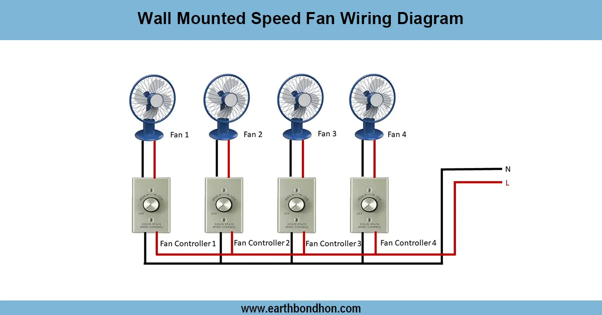
Exhaust fan wiring diagram
Clear wiring diagram and step-by-step guide for wall-mounted speed fans — wiring to switch, speed regulator, capacitor and safety earth for reliable home or commercial installation.
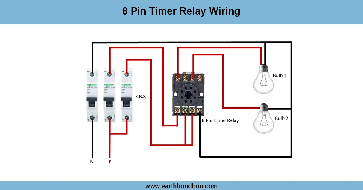
8 Pin Timer Relay Wiring Diagram
Understand 8-pin timer relay wiring with easy diagrams. Learn pinout, connection steps, and functions. Perfect for electricians and electronics hobbyists.
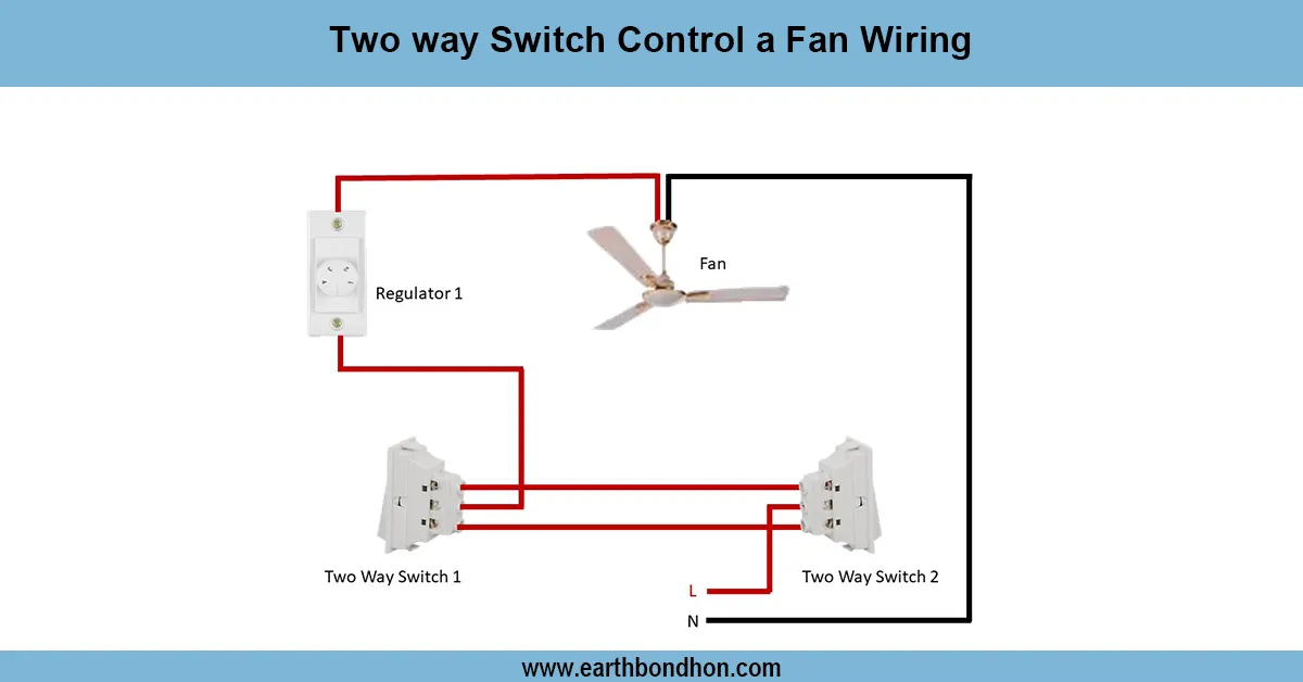
2 way switch control a fan wiring
Easily control your ceiling fan from two different switches using a two-way wiring system. Learn the wiring diagram and connection steps in this guide.