

Series Testing Board Connection
Learn how to wire a series testing board with multiple sockets and bulbs. Ideal for electricians and students testing AC appliances or basic electric setups.

how to make a series tester board
Safe appliance testing is only possible with the help of the Series Testing Board. It works with a lamp connected in series so as to diagnose faults that may include shorts without exposing to full voltage. This is a step-by-step instruction on how to wire a testing board and what each part does, and the formula that is followed in a series resistance. Ideal when applied to beginners, students, and technicians.
Formula & Table Summary:
Formula Used:
Rtotal = R₁ + R₂ + ... + Rₙ
Where:
Rtotal= Total series resistanceR₁, R₂, ...= Resistance of individual elements (bulb, load)
Series testing lamp diagram
A Series Testing Board is a basic electrical device which is employed on electromechanical devices such as low-capacity equipment such as bulbs, fans, chargers, and low-output appliances. It is usually designed to have inbuilt power input, a series lamp (used to restrict current), and one or more output sockets into which the test device is connected. The series bulb is placed as a safety measure where it lights partially when the test device is working or all the way in case of a short-circuit. This installation guards the user and gadget against abrupt harm. The boards are very useful when repairing a device, and they can also be found in laboratories, workshops, and homes. Electrical dangers are a great concern that requires good wiring and insulation. The guide assists you in your knowledge of the procedure (including how to connect sockets, switches, and lamps in series) in making a safe and effective testing board. It also includes a wiring diagram, a table-like summary, and a formulation elucidation to give the concept a simplistic form to the learners and practitioners.
Series connection tester board
| Component | Value / Rating | Function |
|---|---|---|
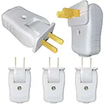
| Input Plug | 230V AC | Power supply |
| Series Lamp | 100W / 200W | Limits current, shows status |
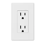
| Output Socket | 2-pin / 3-pin | Connect appliance to test |
| Switch | SPST / DPST | Controls the test circuit |
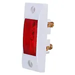
| Indicator Lamp | 1W LED | Visual indicator |
Frequently Asked Questions - Series Testing Board Connection:
What is a series testing board?
It's a tool used to test electrical appliances with a safety bulb connected in series.
Why use a bulb in a series testing board?
To limit current and prevent appliance damage during testing.
Can I use LED instead of an incandescent bulb?
No, incandescent bulbs are preferred for visible current indication.
What type of appliances can I test?
Fans, bulbs, chargers, and low-power AC devices.
How does the bulb indicate a fault?
If the bulb glows fully, the appliance may have a short circuit.
Is it safe for students to use?
Yes, if proper insulation and precautions are followed.
What is the wattage of the series bulb?
Commonly 100W to 200W depending on the appliance.
Can I use multiple sockets on one board?
Yes, but only one appliance should be tested at a time.
Do I need grounding for this board?
Grounding improves safety but is optional for low-power testing.
Where is this setup commonly used?
In homes, repair shops, training labs, and electrician toolkits.
Related Posts
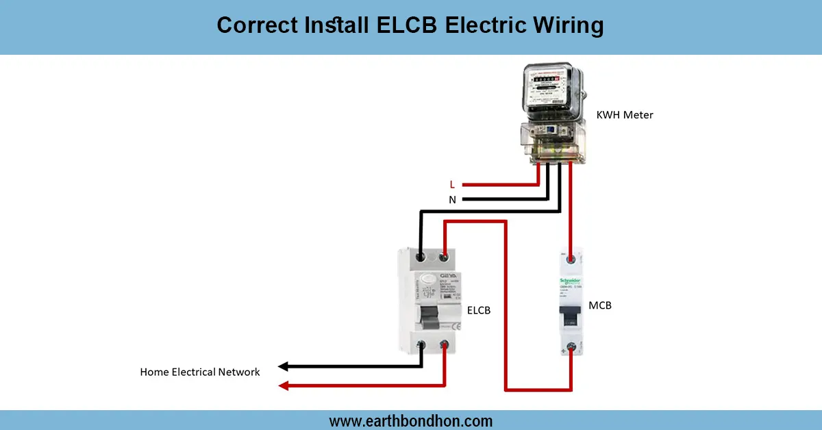
Earth Leakage Circuit Breaker wiring
Learn how to correctly install ELCB wiring to protect against electric shocks and faults. Step-by-step guide for safe electrical wiring with ELCB devices.
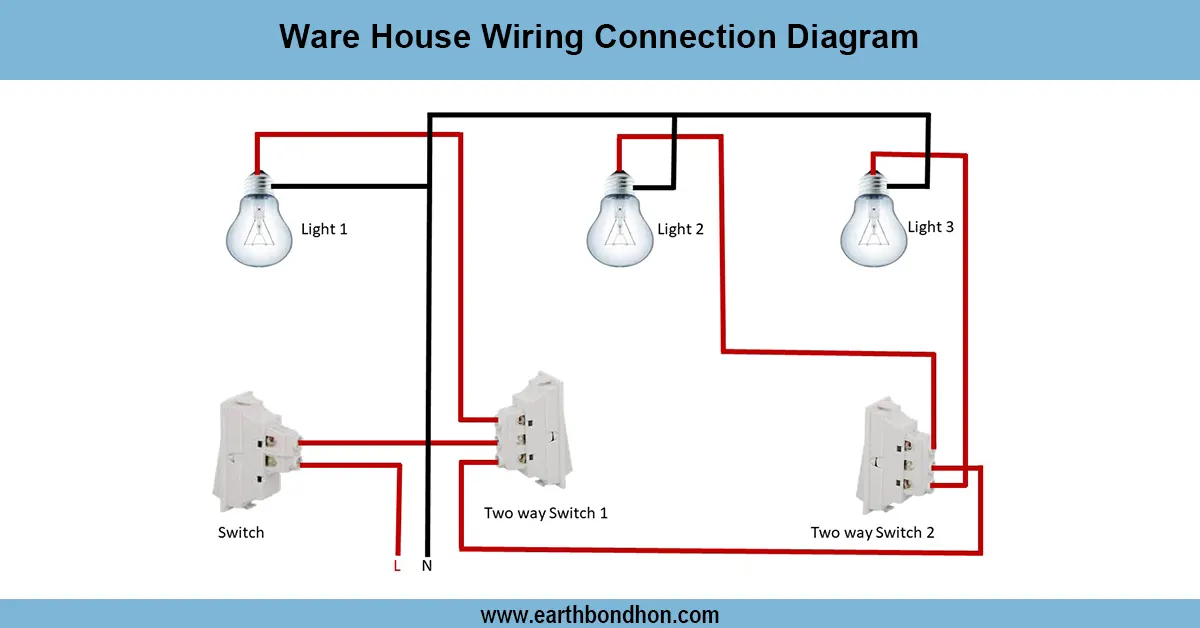
Basic House Wiring
Learn warehouse wiring connection diagrams with clear layouts for lighting, power distribution, and equipment to ensure safety and energy efficiency.
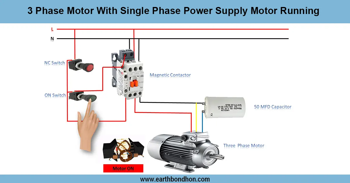
3 Phase Motor in Single Phase Connection
Learn how to run a 3-phase motor on a single-phase power supply using capacitor start or phase converter methods for reliable motor operation.
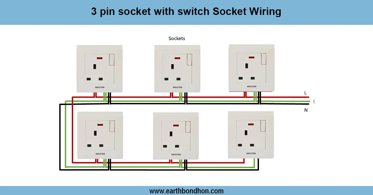
Power Socket Wiring Diagram
Learn how to wire a power socket with safety in mind. This guide includes diagrams, step-by-step instructions, and common wiring FAQs for home and industrial use.
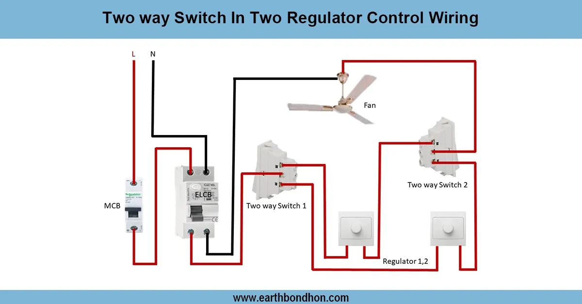
Two way switch fan regulator connection
Wiring diagram for controlling two separate light regulators from two locations using two-way switches for flexible ON/OFF control.

Parallel Circuit with 3 bulbs
Understand how to wire a parallel circuit with three light bulbs. Learn the diagram, current flow, voltage sharing, and total resistance with practical wiring tips.