


Switch and Socket Connection Diagram
Understand switch and socket connection diagrams for safe and efficient home wiring. Step-by-step wiring guide for switches and electrical sockets.

electrical socket wiring
The wiring of electrical connections to the home, such as switch and socket connection diagrams, is shown using a switch and socket connection diagram. Switches to turn lights or devices off and on are connected and disconnected to live wires, whereas sockets give constant power with a live wire, neutral wire, and an earthed wire. Safe and reliable electrical operation is assured by proper wiring with the correct polarity and by grounding. Learning how to read them would aid in installation, fault, and repair in home electrification.
Formula & Table Summary:
Voltage (V): Usually 220-240V AC mains supply
Current (I): Depends on device/load connected
Power (P):P = V × I
Wiring Connections:
- Switch: Live (L) wire connected to switch input, output goes to light/load
- Socket: Live (L), Neutral (N), Earth (E) connected to respective terminals
switch wiring diagram
Switch and socket connection diagram A switch and socket connection diagram enumerates the communication of the electrical switches and sockets in a domestic electrical system. The electricity flow to a light or an appliance is usually controlled using switches, which open and/or close the circuit. Sockets are used to give power fittings to receptacles to plug the electrical devices. The wiring entails the live (L), neutral (N), and earth (E) wires that are properly wired such that they are both safe and functional. This is aimed at having simple wiring of the single-pole switch wiring and the standard socket outlet wiring with proper identification of terminal connections and color coding. Proper wiring eliminates the possibilities of electrical faults, shocks, and fire. The diagram can even guide electricians and Hobbyists in a series of wiring where the switch turns on the desired load and the socket has constant power. Contemporary houses are connected with color-marked wires like brown or red to communicate live, blue or black to neutral, and green/yellow to earth. Correct plugging and grounding of the socket is very important as far as electrical safety is concerned.
switch wiring diagram
| Component | Wire Color | Terminal | Function |
|---|---|---|---|
| Live Wire (L) | Brown / Red | Switch Input / Socket L Terminal | Carries current to device |
| Neutral Wire (N) | Blue / Black | Socket N Terminal | Completes electrical circuit |
| Earth Wire (E) | Green / Yellow | Socket E Terminal / Switch Frame | Safety grounding |
| Switch | N/A | Breaks or completes Live wire circuit | Controls power to load |
Frequently Asked Questions - Switch and Socket Connection Diagram:
What color wires are used for live, neutral, and earth?
Live is brown/red, neutral is blue/black, earth is green/yellow.
How is a switch connected in a lighting circuit?
The live wire is connected to the switch input, and switch output connects to the light.
Why is the earth wire important in socket wiring?
It provides a safety path to prevent electric shocks in case of faults.
Can I connect multiple sockets on the same circuit?
Yes, sockets can be wired in parallel on the same circuit.
What happens if live and neutral are reversed in socket wiring?
It can be dangerous, causing electric shock risk or malfunctioning devices.
How do I identify terminals on a socket?
Terminals are marked L for live, N for neutral, and E for earth/ground.
Is it safe to install switches and sockets myself?
Only if you are qualified or follow local electrical codes and safety guidelines.
What wire gauge is typically used for home switch and socket wiring?
Usually 1.5mm² or 2.5mm² cable depending on load and regulation.
Can a switch control multiple lights?
Yes, a switch can control several lights wired in parallel.
What is the difference between single-pole and double-pole switches?
Single-pole switches break only the live wire, while double-pole switches break live and neutral both.
Related Posts
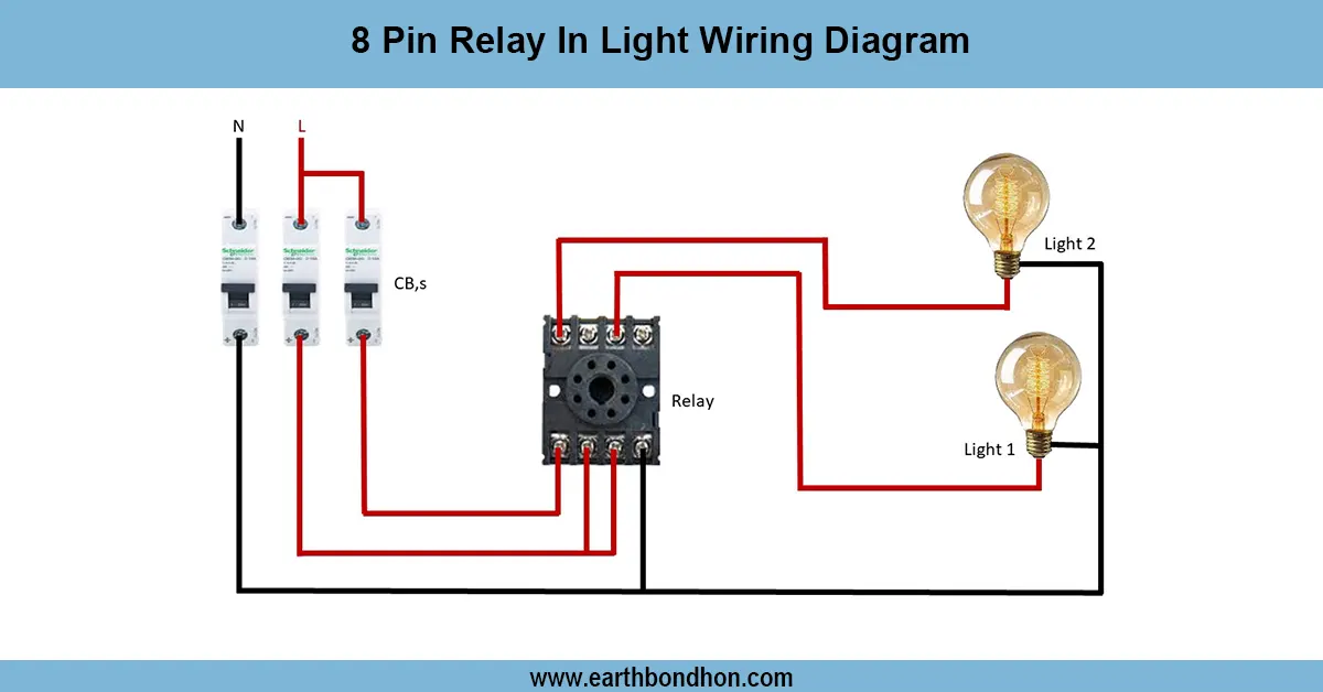
8 Pin Relay In Light Wiring Diagram
Understand how to wire an 8-pin relay for controlling lights using a switch or sensor. Ideal for automation, safety, and efficient lighting systems.
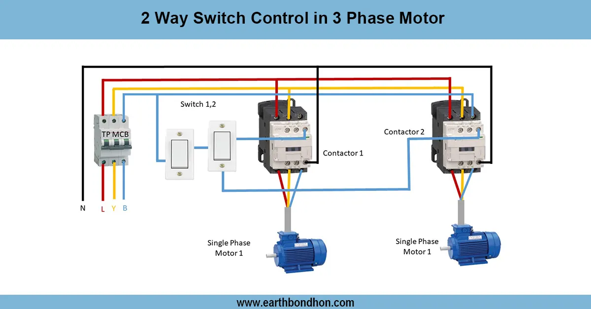
2-way Switch Control in 3-Phase Motor
Learn how to use a 2-way switch control for a 3-phase motor to operate it from two locations, including wiring diagrams and safety tips for reliable control.
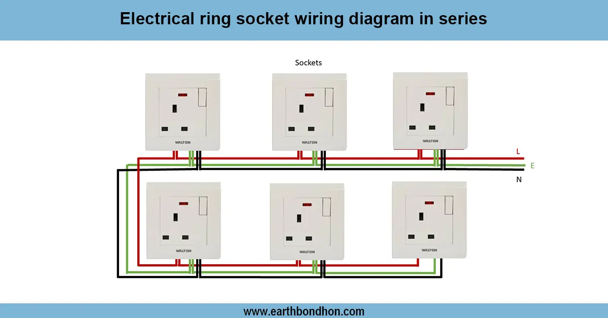
Electrical Ring Socket Connection
Learn how electrical ring socket wiring works in homes. Understand circuit design, safety, and layout in low-voltage electrical installations.

3-Phase ATS circuit wiring
Detailed 3 phase ATS wiring diagram for automatic transfer switch installation to switch power between mains and generator safely and efficiently.
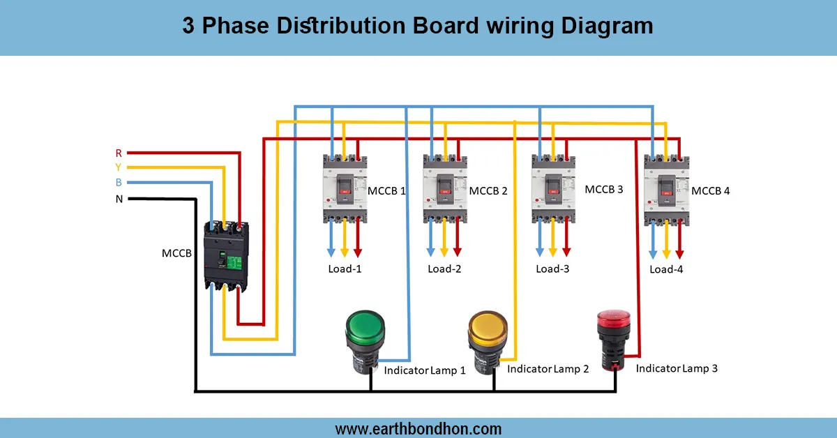
3 Phase Distribution Board wiring
Comprehensive 3-phase distribution board wiring guide for safe and efficient power distribution with MCCB, breakers, neutral, and earth connections.
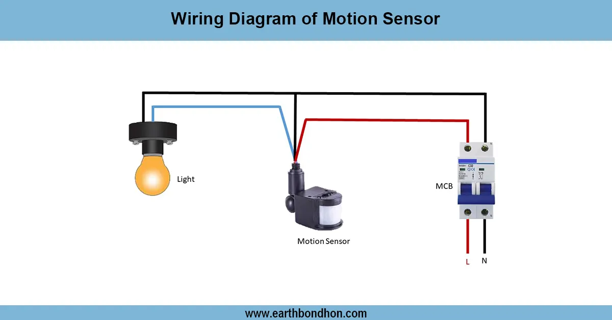
Motion Sensor connection
Step-by-step wiring diagram of a motion sensor connected to a light circuit for automatic ON/OFF control based on detected movement.