


Manual Light sensor connection for street light
Wiring diagram for 3-phase electric systems using light sensors to automate lighting control, improving energy efficiency and safety in industrial and commercial setups.

light sensor electric wiring
The 3 phase electric light sensor wiring system simplifies the process of lighting control by turning 3 phase power on or off to lights on the basis of the ambient light sensed by the sensor.
3 Phase Light Sensor Wiring Summary:
Power Supply: 3 phase lines L1, L2, L3 supply lighting load via contactor
Light Sensor: Detects ambient light and controls relay coil
Contactor Coil: Energized by sensor output to switch lighting circuit
Load: 3 phase lighting fixtures connected through contactor
Protection: Circuit breakers and fuses for safety
commercial light sensor installation
Owing to a light sensor in its 3 phase electric wiring system, the lights can be automatically controlled whenever adjusting the ambient light conditions. The light sensor will read the amount of natural light and switch the 3 phase lighting circuit ON or OFF via the relay or the contactor connected. The installation is widely adopted in industrial, commercial or outdoor lighting options where the installation is meant to limit manual intervention and increase the energy saving. The wiring would be the output signal of the sensor would go to the control coil of a 3 phase contactor or relay, and the main 3 phase lines powers the lighting load. Appropriate installation entails proper handling of sensor wiring, without overloading the sensor with voltage well within ratings and the proper overload protection.
energy-saving lighting circuit
| Component | Connection | Purpose |
|---|---|---|
| 3 Phase Power (L1, L2, L3) | Connected to main contacts of contactor | Supplies power to lighting load |
| Light Sensor Output | Connected to contactor coil control circuit | Activates lighting based on ambient light |
| Contactor Coil (A1, A2) | Energized by sensor output and power supply | Switches lighting circuit ON/OFF |
| Lighting Load | Connected through contactor main contacts | Receives controlled 3 phase power |
| Protection Devices | Circuit breakers and fuses on supply lines | Protect wiring and equipment from faults |
Frequently Asked Questions - Manual Light sensor connection for street light:
What is a light sensor in 3 phase wiring?
A device that detects ambient light to control lighting automatically.
How does the sensor control 3 phase lights?
It energizes the contactor coil to switch power ON or OFF.
Where is the sensor installed?
In a location with good exposure to ambient light.
Can it save energy?
Yes, by switching lights off when enough daylight is present.
Is special wiring needed for the sensor?
Yes, sensor output wiring connects to the contactor coil control.
What protection devices are recommended?
Circuit breakers and fuses for safe operation.
Can this be used outdoors?
Yes, suitable sensors and enclosures must be used.
What voltage does the sensor use?
Depends on sensor type; common types use 24V or 230V control voltage.
Can it control other loads besides lighting?
Yes, any load controlled via contactor coil.
Who should install the system?
Qualified electricians with experience in 3 phase and control wiring.
Related Posts

Voltage monitor Relay connection
Learn how to wire a voltage monitor relay in a DOL starter to protect 3-phase motors from phase loss, phase reversal, and voltage faults with easy connection steps.
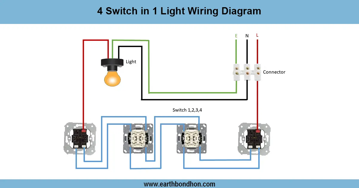
4 Switch 1 Light Control Wiring
A wiring diagram showing how to control one light using four different switches from different locations. Ideal for staircases or long corridors.

Parallel Circuit with 3 bulbs
Understand how to wire a parallel circuit with three light bulbs. Learn the diagram, current flow, voltage sharing, and total resistance with practical wiring tips.
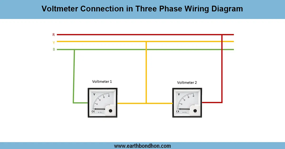
Three phase voltmeter connection
volts times the square root of 3, which happens to be rounded off to 1.732. For 2 lines each carrying 120 volts, the calculation for this is 120 volts times 1.732, and the result is rounded up to 208 volts.
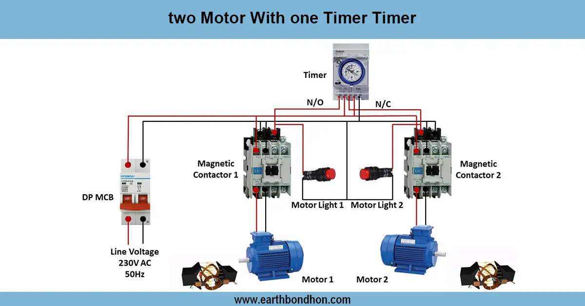
Motor with on delay Timer
Wiring diagram for controlling two motors with a single timer to automate motor operation in industrial, agricultural, or manufacturing applications.
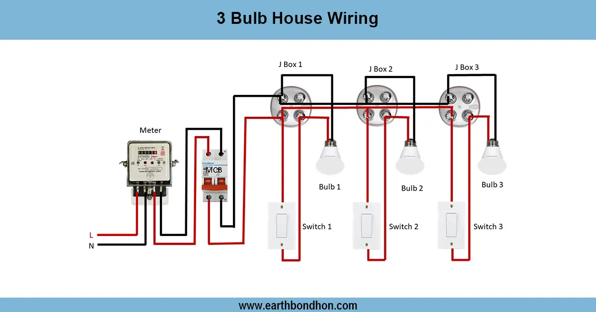
Single Phase House wiring circuit diagram
Simple 3-bulb house wiring diagram showing connections of bulbs with switches and power supply for safe and efficient home lighting control.