


Two way switch fan regulator connection
Wiring diagram for controlling two separate light regulators from two locations using two-way switches for flexible ON/OFF control.

two way switch two regulator wiring
A two-way switch three regulator means that two of the regulators can be controlled independently in two different locations with pairs of SPDT switches and traveler wiring on each circuit.
Formula & Table Summary:
Components: Four SPDT switches (two pairs), two light regulators, live (L), neutral (N), traveler wires.
Connections: Each pair of two way switches connects via traveler wires; switch commons connect to live supply and respective regulator inputs; regulators connect to neutral.
Operation: Each regulator controlled independently by toggling either switch in its pair.
Safety: Turn off power before installation and use appropriate wire gauges and protections.
| Component | Connection | Function |
|---|---|---|
| Switch Pair 1 Common | Connect to Live supply | Power input for Regulator 1 |
| Switch Pair 1 Travelers | Connect between Switch 1 and 2 | Switching paths for Regulator 1 |
| Regulator 1 Input | Connect to Switch Pair 1 Common terminal | Control input |
| Switch Pair 2 Common | Connect to Live supply | Power input for Regulator 2 |
| Switch Pair 2 Travelers | Connect between Switch 3 and 4 | Switching paths for Regulator 2 |
| Regulator 2 Input | Connect to Switch Pair 2 Common terminal | Control input |
| Neutral | Connects to Regulators | Completes circuit |
electrical wiring two regulators
This wiring is to activate two independent light regulator found on two different switch location through two way switches. The different regulators operate individual lights/fans allowing them to be switched ON/OFF independently at two locations. The wiring includes two sets of two-pole-two-throw (SPDT) switches,one set with each regulator,wired with traveler cables between the two switch locations. The individual regulator is connected to individual switch common terminal and neutral. The arrangement is convenient when it is used in rooms, which have several entries or with the aim of regulating various light segments conveniently.
two way switch installation
| Regulator 1 Switch Positions | Regulator 2 Switch Positions | Regulator 1 Status | Regulator 2 Status |
|---|---|---|---|
| Up - Up | Up - Up | OFF | OFF |
| Up - Down | Down - Up | ON | ON |
| Down - Up | Up - Down | ON | ON |
| Down - Down | Down - Down | OFF | OFF |
Frequently Asked Questions - Two way switch fan regulator connection:
What is a two way switch for two regulators?
A wiring system allowing control of two separate light regulators from two locations.
How many switches are used?
Four SPDT switches arranged in two pairs.
Can the two regulators be controlled independently?
Yes, each regulator has its own switch pair.
Are traveler wires needed?
Yes, for each switch pair connecting two locations.
Where do the live wires connect?
To the common terminals of each switch pair.
Is neutral connected to switches?
No, neutral connects directly to the regulators.
Can this wiring be used for fans as well?
Yes, for any device controlled by regulators.
Is safety important?
Yes, always turn off power and use proper wiring.
Can I install this wiring myself?
Only if familiar with electrical systems and safety.
What tools are required?
Screwdrivers, wire stripper, voltage tester, and electrical tape.
Related Posts
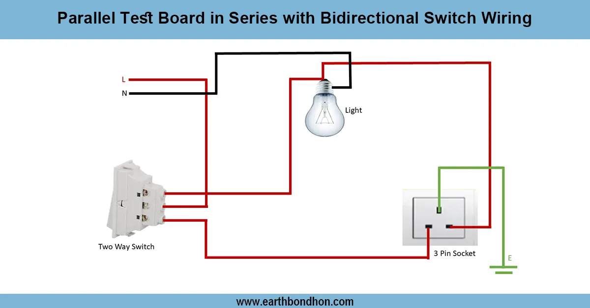
Series Testing Board Wiring
Learn how to wire a series testing board to safely check appliances, identify faults, and test current flow without damaging electrical equipment.
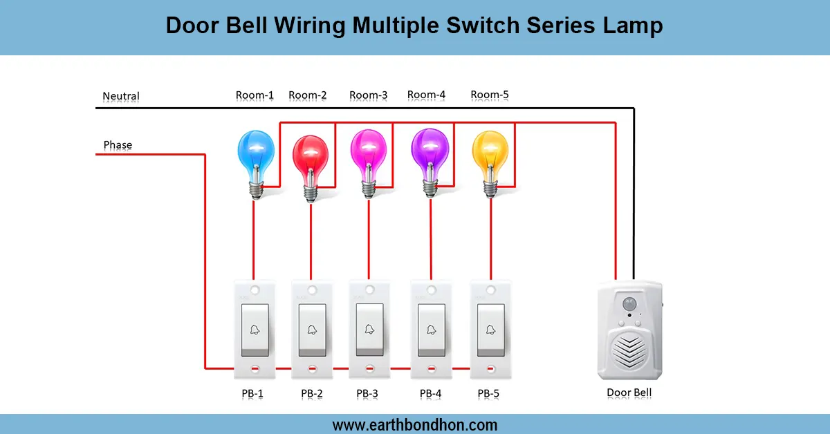
Door Bell wiring Diagram
Learn the basic doorbell wiring diagram, connections, and components for a reliable home doorbell system installation with easy step-by-step guidance.
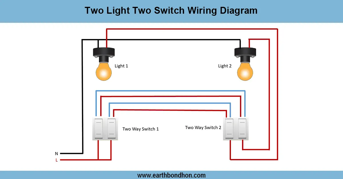
1 Light controlled by 2 switches
Control one light using two switches located at different positions with a simple two-way switch wiring setup. Ideal for hallways, staircases, and bedrooms.
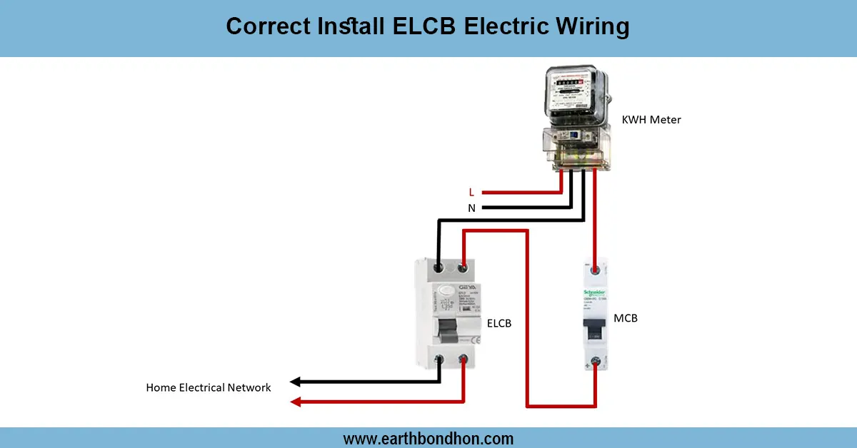
Earth Leakage Circuit Breaker wiring
Learn how to correctly install ELCB wiring to protect against electric shocks and faults. Step-by-step guide for safe electrical wiring with ELCB devices.

3 Phase SPD Connection
Detailed 3 phase SPD connection diagram showing how to wire surge protection devices to safeguard electrical systems from transient overvoltages.
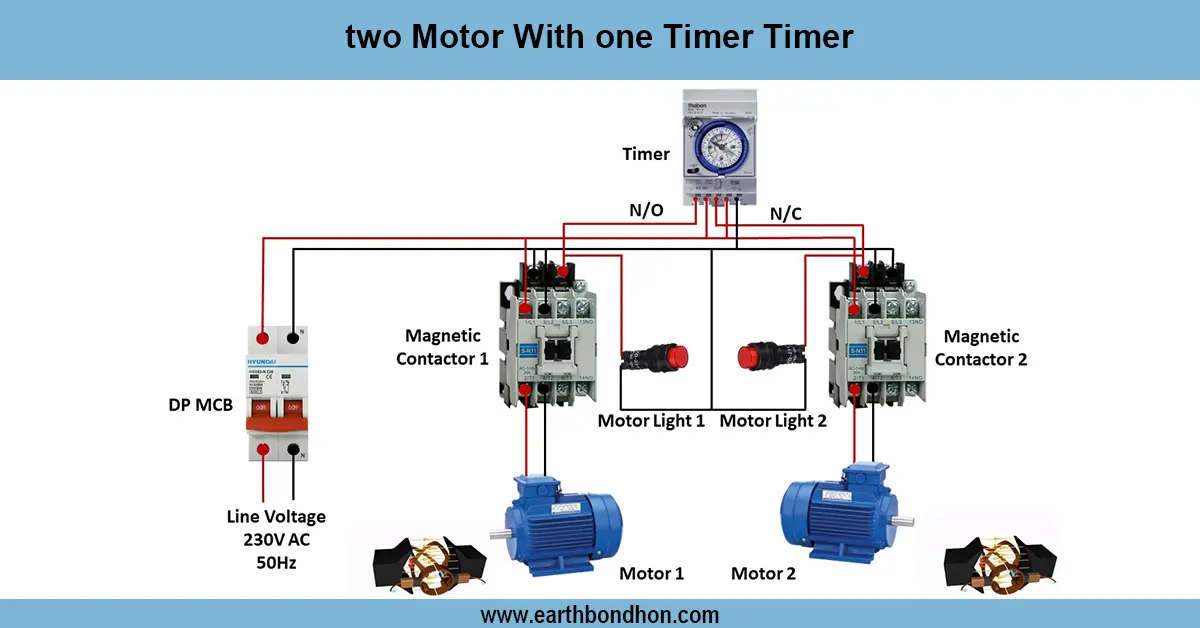
Motor with on delay Timer
Wiring diagram for controlling two motors with a single timer to automate motor operation in industrial, agricultural, or manufacturing applications.