


3 Phase SPD Connection
Detailed 3 phase SPD connection diagram showing how to wire surge protection devices to safeguard electrical systems from transient overvoltages.

3 phase electrical protection
A 3 phase SPD connection are wired aesthetic surge protection devices on each of the 3 phases and divert unfortunate surges safely to ground protecting electrical equipment against damage caused by transient surges.
3 Phase SPD Wiring Summary & Components:
Connection Points: L1, L2, L3, Neutral (N), and Earth (PE)
Purpose: Divert transient overvoltages to ground
Location: Near main distribution panel
Grounding: Essential for SPD operation and safety
surge arrestor connection
A 3 phase SPD (Surge Protection Device) connection diagram shows the pattern of connecting surge arrestors to a three phase electrical system to protect against voltage spikes in the power supply as a result of lightning or a switching surge. During proper installation the SPD should be connected to all three phases (L1, L2, L3) and neutral (N) lines in a such a way that transient overvoltages are safely discharged to the ground. The SPD is placed very close to the main panel or distribution board as a form of protection to sensitive equipment downstream. Earthing is essential to the functioning and performance of SPD. The given connection arrangement would tame the disruption and damage of electrical systems due to voltage spikes that may occur (minimized). The installation of SPD in 3 phase industrial or commercial power systems should ensure care is taken to adhere to any specifications provided by manufacturers and electrical codes to install the products effectively and safely.
three phase surge protector wiring
| Terminal | Connection | Function |
|---|---|---|
| L1 | Connected to phase 1 line | Surge protection on phase 1 |
| L2 | Connected to phase 2 line | Surge protection on phase 2 |
| L3 | Connected to phase 3 line | Surge protection on phase 3 |
| Neutral (N) | Connected to system neutral | Reference for surge diversion |
| Earth (PE) | Connected to grounding system | Safely diverts surge current to ground |
Frequently Asked Questions - 3 Phase SPD Connection:
What is an SPD?
A Surge Protection Device protects electrical systems from transient voltage surges.
Why is SPD important in 3 phase systems?
It prevents damage to equipment from voltage spikes on all phases.
Where should SPDs be installed?
Near the main distribution board for maximum protection.
How is SPD connected in a 3 phase system?
Connected across L1, L2, L3, neutral, and earth.
Is grounding necessary for SPD?
Yes, proper grounding is essential for effective surge diversion.
Can SPD protect against lightning strikes?
It helps protect against surges caused by lightning but not direct strikes.
How often should SPD be checked?
Regularly as per manufacturer recommendations to ensure functionality.
Can SPD be used in residential systems?
Yes, especially in areas prone to lightning or electrical disturbances.
What happens if SPD fails?
It may not protect equipment from surges, increasing risk of damage.
Does SPD reduce electricity consumption?
No, it protects equipment but does not affect power usage.
Related Posts
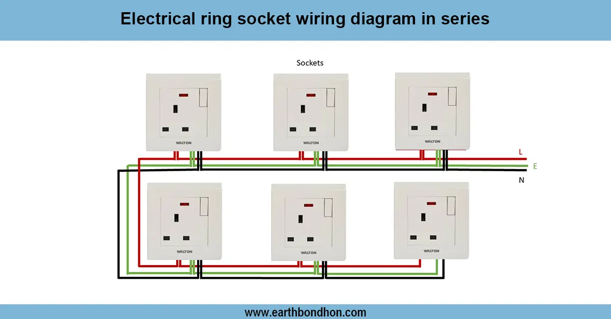
Electrical Ring Socket Connection
Learn how electrical ring socket wiring works in homes. Understand circuit design, safety, and layout in low-voltage electrical installations.
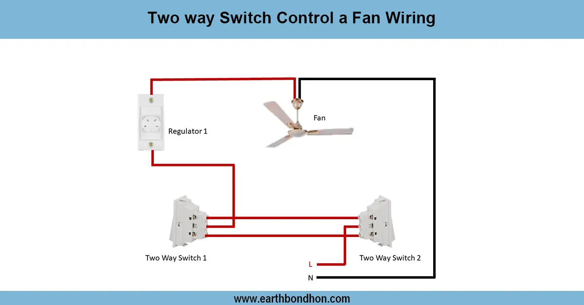
2 way switch control a fan wiring
Easily control your ceiling fan from two different switches using a two-way wiring system. Learn the wiring diagram and connection steps in this guide.
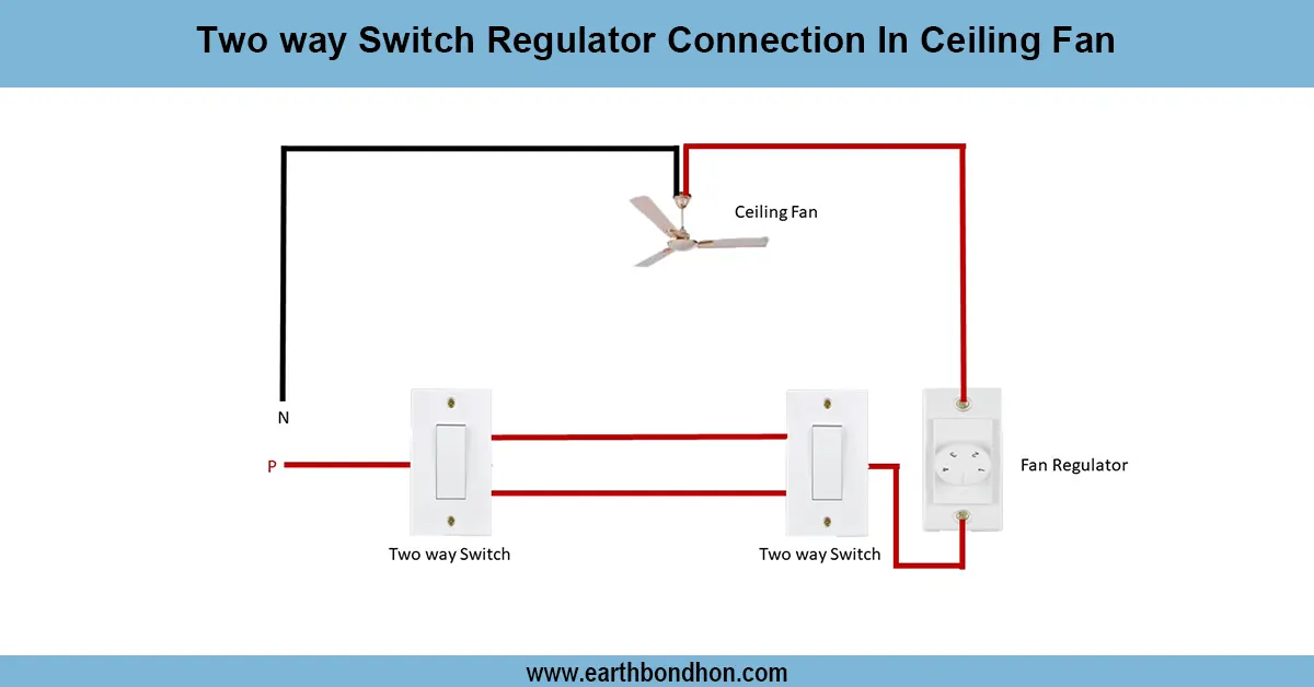
Ceiling Fan Regulator connection
Wiring diagram showing how to connect a two way switch with a regulator to control ceiling fan speed and ON/OFF from two locations.
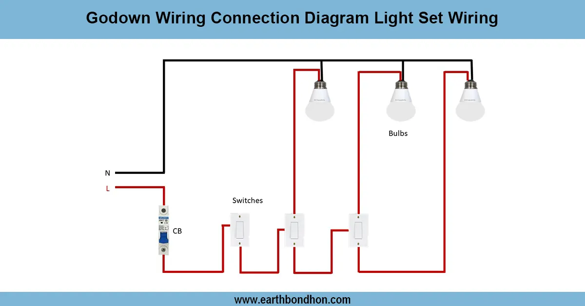
Godown wiring circuit diagram
Learn how Godown wiring works to light one room at a time using multiple switches. Ideal for warehouses, corridors, and storage areas with energy-saving control.
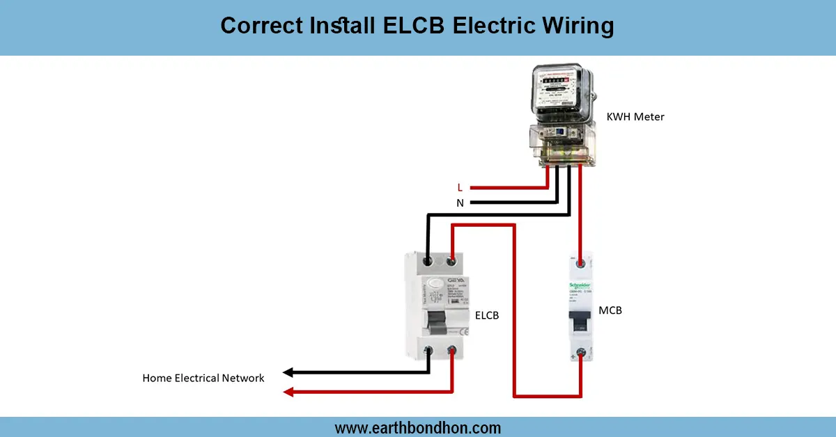
Earth Leakage Circuit Breaker wiring
Learn how to correctly install ELCB wiring to protect against electric shocks and faults. Step-by-step guide for safe electrical wiring with ELCB devices.

3 Switch 1 Light Wiring Diagram
Learn how to control one light using three switches with step-by-step wiring diagrams, circuit explanation, and real-life application tips for efficient electrical setups.