


Godown wiring circuit diagram
Learn how Godown wiring works to light one room at a time using multiple switches. Ideal for warehouses, corridors, and storage areas with energy-saving control.

godown switch connection
An example of what a wiring circuit diagram of a godown looks like is that of how we can use several lights having an individual switch with only one light ON during a circuit. This is a sequential lighting system that improves energy and is mostly applicable in long corridors, warehouses, or storage places. The circuit, which is designed in the godown with switches, ensures that no more than a single bulb is turned ON at a time, as each switch turns the previous one OFF and the current one ON. This tutorial gives the concept of working, arrangement, formula, and application of godown wiring.
Formula & Table Summary:
Formula: Only one switch (Sn) connects phase to the corresponding lamp (Ln) → Light ON = SWn = ON; All Other SW = OFF
one switch one light control
Godown wiring is one of the common means, which is applied in godowns, long corridors, and production halls where one point of light is necessary at a time. The idea itself is rather straightforward but still helpful: a couple of lights are linked by separate switches, and yet, only one of them works at any one time. This arrangement is energy efficient and prevents the use of lights in the unutilized areas. Each of the switches would be located next to the respective room or area so the staff could switch on a light only when entering that particular area. After pressing one of the other switches, the lamp that has been turned on goes off, and the one that has been selected becomes lit. This not only makes godown wiring economical but also safer since the overall load will be minimized. It is commonly applied in basements, schools, hospitals, and warehouses.
godown wiring diagram
| Switch No. | Switch Position | Light Status | Energy Usage |
|---|---|---|---|
| SW1 | ON | L1 ON | Active |
| SW2 | ON | L2 ON | Active |
| SW3 | OFF | OFF | Inactive |
| SW4 | OFF | OFF | Inactive |
Frequently Asked Questions - Godown wiring circuit diagram:
What is godown wiring?
It is a wiring method where only one light remains ON at a time, ideal for corridors and warehouses.
Where is godown wiring used?
Used in storage rooms, basements, godowns, long hallways, and industrial areas.
How does godown wiring save energy?
Only one light is powered at a time, reducing overall electricity usage.
Can godown wiring be automated?
Yes, using relays or smart switches for automated light control.
What switch type is used in godown wiring?
Standard one-way (SPST) switches are commonly used.
Is neutral shared in godown wiring?
Yes, all lights share the same neutral line.
Can this system control fans?
No, it is designed specifically for light control.
Is this wiring suitable for homes?
Rarely; it's more suited for industrial and commercial spaces.
What safety precautions should be followed?
Use proper MCBs, wiring gauges, and ensure all joints are insulated.
How many switches can be used?
As many as required; each light needs a dedicated switch.
Related Posts
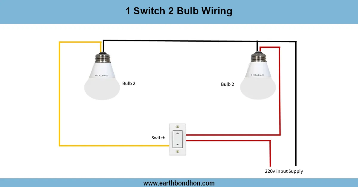
2 Lights 1 Switch Wiring
Learn how to wire 2 lights with 1 switch using a parallel circuit. This guide includes diagrams, FAQs, formulas, and real data to simplify your electrical project.
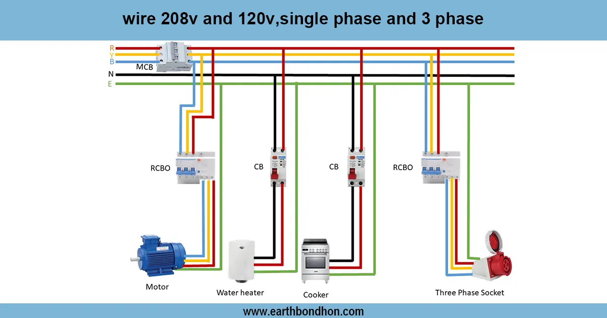
Single house wiring
Comprehensive guide on wiring 208V and 120V in single phase and 3 phase systems including color codes, connections, and safety tips for residential and industrial use.
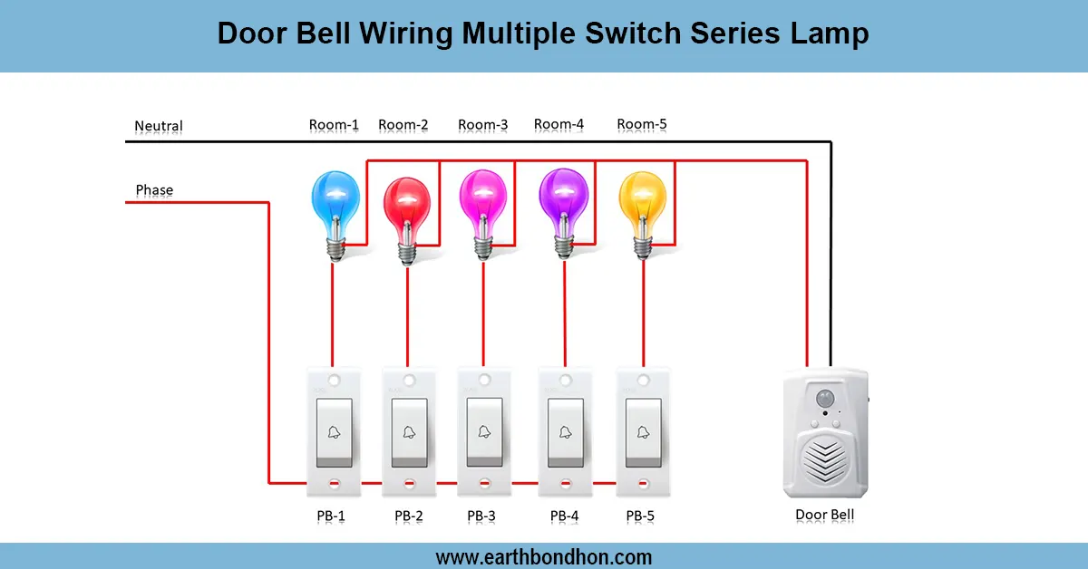
Door Bell wiring Diagram
Learn the basic doorbell wiring diagram, connections, and components for a reliable home doorbell system installation with easy step-by-step guidance.

3 Phase Motor Forward Reverse Wiring Diagram
Learn the wiring of a 3-phase motor forward-reverse mini changeover switch with a clear diagram, enabling easy motor direction control and safe operation.
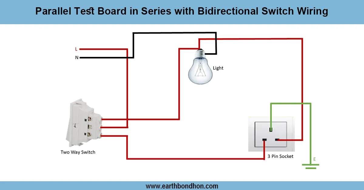
Series Testing Board Wiring
Learn how to wire a series testing board to safely check appliances, identify faults, and test current flow without damaging electrical equipment.
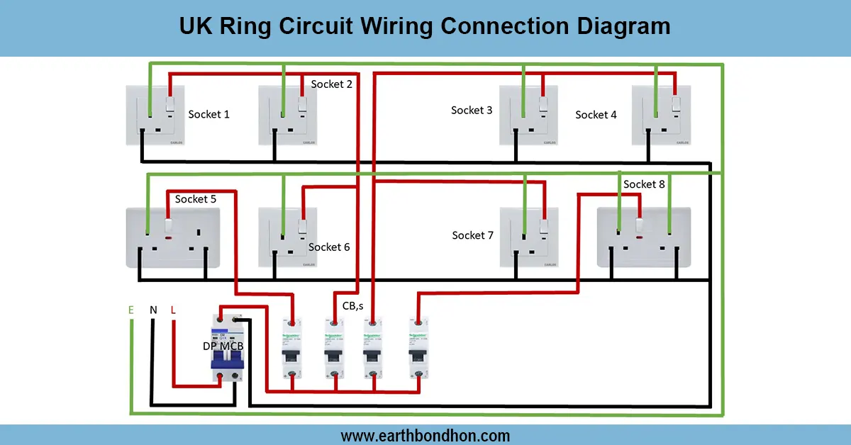
Electrical Ring socket connection
UK ring circuit wiring diagram showing socket connections, protective devices, and proper wiring method for safe and efficient power distribution.