


3 Phase Motor Star Connection Diagram
Learn 3-phase motor capacitor star connection wiring for starting and running capacitors, ensuring efficient motor operation with clear wiring steps.

3 phase motor capacitor wiring
In the wiring through a capacitor star connection used in 3-phase motors, capacitors are networked in a star connection, intersecting the windings of a motor to form phase shifting to start and run. It is designed to balance voltages and advanced torque of motors, as it is a good match in heavy-duty applications. The right wiring and capacitor choice make the motor most efficient and can last long time. .
3 Phase Motor Capacitor Star Connection Formula & Summary:
Voltage per phase (Vph):Vph = VL / √3
Capacitor Current (Ic):Ic = 2π f C Vph
Power (P): Capacitors improve starting torque and power factor
Wiring Connections: Each capacitor connected from phase to neutral point forming a star (Y) connection
motor capacitor connection diagram
Another way of connecting capacitors in star (Y) so they are wired to a 3-phase motor to enhance starting torque and efficient operation is the 3-phase motor capacitor star connection wiring. The wiring arrangement comprises starting and running capacitors with the windings of the motor connected in star form, with the capacitors connected between each phase and the neutral point. The star connection results in balanced voltage to capacitors and windings, which also relieves most of the electrical stress and improves the performance of the motor. Adequate wiring prevents jerky start-up of the motor and makes it operate efficiently with minimal power wastage. There is step-by-step wiring, capacitor choice, and safety considerations in this guide. It is applied extensively in the industry and business sectors where a sure restart and working environment are required.
motor starting capacitor wiring
| Component | Parameter | Value / Formula | Description |
|---|---|---|---|
| Line Voltage (VL) | - | 400 V (typical) | Voltage between two phases |
| Phase Voltage (Vph) | Vph = VL / √3 | 230 V approx. | Voltage per winding in star |
| Capacitor Current (Ic) | Ic = 2π f C Vph | Depends on capacitance and frequency | Current through the capacitor |
| Capacitor Connection | Star (Y) | Each capacitor connected the phase to the neutral | Balances phase voltage and improves start |
Frequently Asked Questions - 3 Phase Motor Star Connection Diagram:
What is star connection in a 3 phase motor capacitor wiring?
Star connection connects each capacitor from a phase to the neutral point forming a Y shape.
Why are capacitors used in 3 phase motor star connection?
Capacitors improve starting torque and correct power factor by creating phase shifts.
What types of capacitors are used in motor wiring?
Start capacitors and run capacitors are commonly used in star connection.
How is the phase voltage calculated in star connection?
Phase voltage Vph = Line voltage VL divided by square root of 3.
Can star connection capacitors be connected incorrectly?
Yes, incorrect wiring can cause motor malfunction or damage.
What is the effect of star connection on motor efficiency?
It improves efficiency by balancing voltages and reducing electrical losses.
Are star connected capacitors used in all 3 phase motors?
No, only motors requiring phase shifting for start or power factor correction use them.
How to select capacitor value for star connection?
Capacitor value depends on motor ratings, voltage, and frequency specifications.
Can star connection be used for both start and run capacitors?
Yes, both capacitor types can be wired in star configuration for optimal performance.
Is safety grounding important in motor capacitor wiring?
Absolutely, proper grounding prevents electrical hazards and equipment damage.
Related Posts
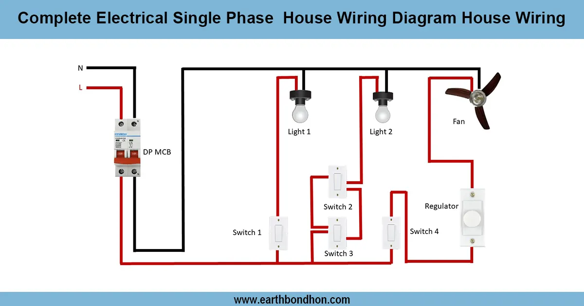
Single Phase House Wiring Diagram
Understand single-phase house wiring diagrams with clear steps for safe, efficient, and reliable home electrical connections.
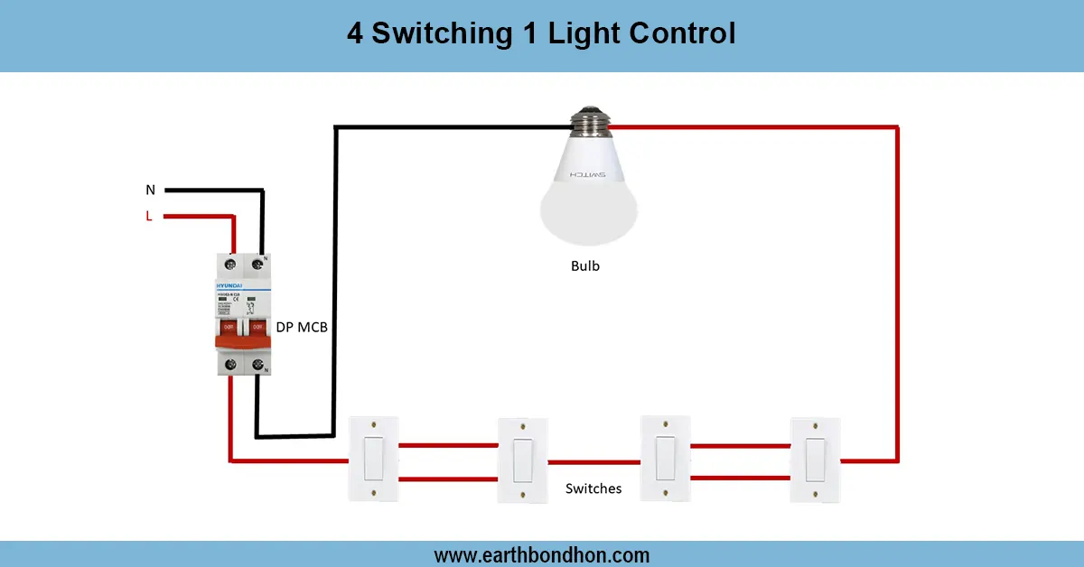
4 Switches 1 Light Control
Learn how to wire 4 switches to control 1 light from multiple locations using intermediate and two-way switches for staircases, hallways, or large rooms.
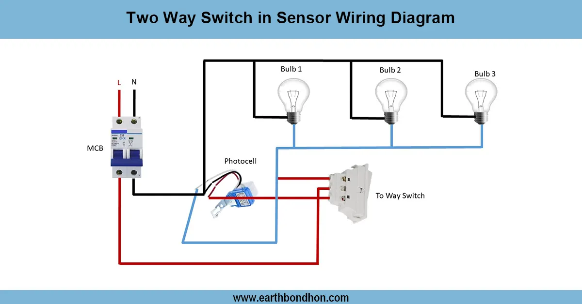
Two way light switch wiring
Wiring diagram showing how to connect a two-way switch with a motion sensor to control a light from two locations with automatic and manual override.
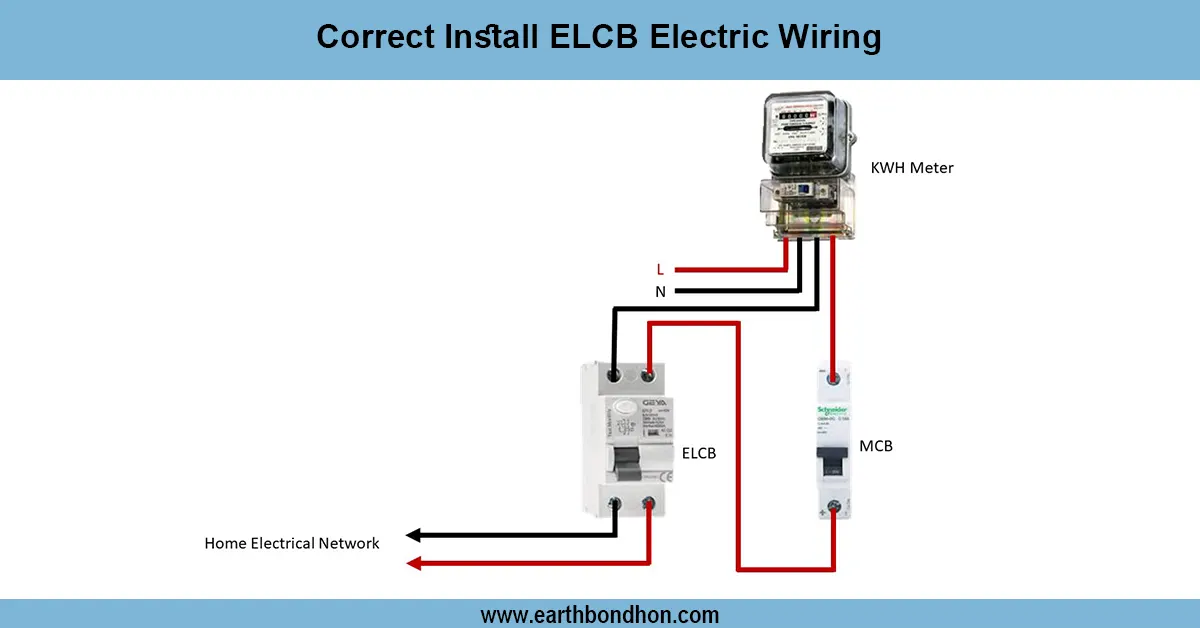
Earth Leakage Circuit Breaker wiring
Learn how to correctly install ELCB wiring to protect against electric shocks and faults. Step-by-step guide for safe electrical wiring with ELCB devices.

Water level controller wiring
Clear wiring diagram for water level controllers, showing connections to sensors, pumps, power supply, and relays for automatic water level management.
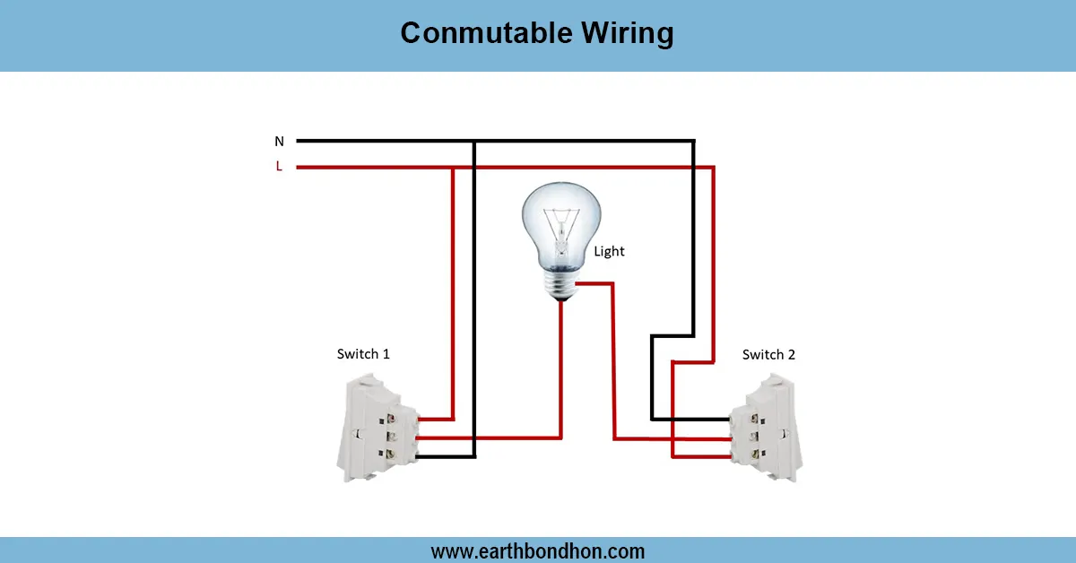
Commutable light Wiring Diagram
Conmutable wiring allows controlling a single light from two switches, ideal for staircases or hallways, using two-way (SPDT) switches for convenience and safety.