


Hospital wiring Diagram
Understand hospital wiring diagrams, including emergency systems, isolation panels, and backup supplies for safe and reliable healthcare facility operations.

electrical diagram for hospitals
A wiring diagram of a hospital is an electrical diagram that covers the entirety of the electrical design system of the hospital and will guarantee safe and efficient functioning of all systems within the healthcare facility. These diagrams are in place because of emergency backup power, patient room lighting, and nurse call systems, etc, and are governed by nasty codes of practice to safeguard patients and employees. Isolation transformers, two power sources, fire alarm circuits, and communication lines are the key equipment. Electrical wiring in the hospital should be well designed and maintained to ensure that healthcare is provided without any disturbances, particularly in critical units such as the operating theaters, ICUs and labs.
hospital Summary:
- Power Requirements Formula:
P = V × I(Power = Voltage × Current) - Load Distribution Formula:
Total Load (kW) = Σ (Load per Circuit)
medical building wiring
A hospital wiring diagram includes the planned electrical system layout of a medical institution, including power, lighting, emergency backup, patient care circuit, and necessary communications. Such diagrams will provide a safe electrical supply to vital medical equipment, nurse call systems, and isolation panels within the ICU and OT rooms. The main amenities consist of redundant power (UPS & generators), fire alarm wiring, and low-voltage signaling to provide an automated level of monitoring. Good wiring ensures that there is continuity in the medical business, minimizes risk, and adheres to the international electric specifications such as IEC 60364 and NFPA 99. The diagrams in hospitals will generally be framed to accommodate safety, redundancy, and regulatory compliance needed to accommodate life-saving systems 24 hours a day.
hospital wiring diagram
Sample Data Table
| Area | Voltage (V) | Load (kW) | Backup Source | Notes |
|---|---|---|---|---|
| ICU Room | 230 | 3.5 | UPS + Generator | Isolation transformer used |
| Operation Theater (OT) | 230 | 5.0 | UPS + Generator | Dedicated circuit |
| General Ward | 230 | 2.0 | Mains | Nurse call system installed |
| Lab Equipment Area | 400 | 6.0 | Generator | 3-phase distribution required |
| Fire Alarm & Emergency | 24 DC | 0.5 | Battery Backup | Separate fire circuit line |
Frequently Asked Questions - Hospital wiring Diagram:
What is a hospital wiring diagram?
It’s a layout showing how electrical systems are distributed across a hospital.
Why is isolation wiring used in hospitals?
To protect sensitive equipment and patients from electrical faults.
What standards apply to hospital electrical systems?
IEC 60364, NFPA 99, and local codes apply.
How is backup power wired in hospitals?
Through UPS systems and diesel generators connected to critical circuits.
What is the purpose of nurse call system wiring?
To enable fast communication between patients and medical staff.
Can hospitals use regular wiring systems?
No, hospitals need specialized redundant and isolated wiring systems.
What is the voltage level used in hospitals?
Typically 230V single-phase and 400V three-phase systems are used.
How are fire alarms integrated?
Using 24V DC lines with central fire panels and alarms.
What is the role of a panel board in hospitals?
It distributes power to specific departments and critical circuits.
Are medical device circuits separated?
Yes, dedicated and isolated circuits are used for medical equipment.
Related Posts
Basic Electrical wiring
Understand the fundamentals of basic electrical wiring for home or industrial use. Covers switches, sockets, lights, circuit breakers, and safety essentials.

Water level controller wiring
Clear wiring diagram for water level controllers, showing connections to sensors, pumps, power supply, and relays for automatic water level management.
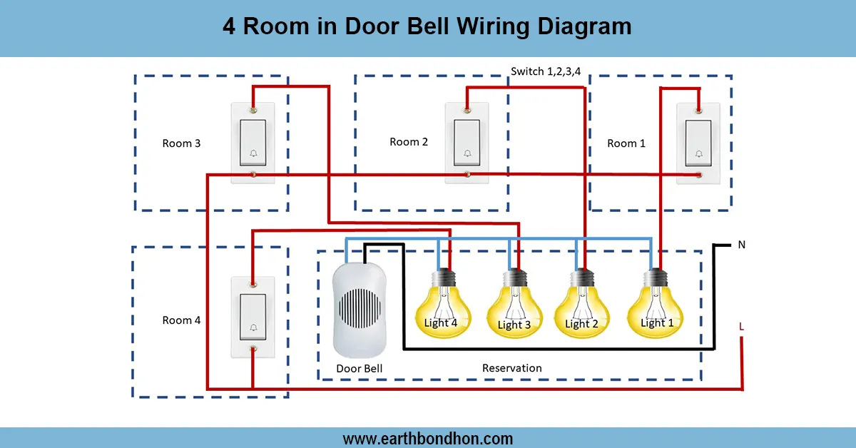
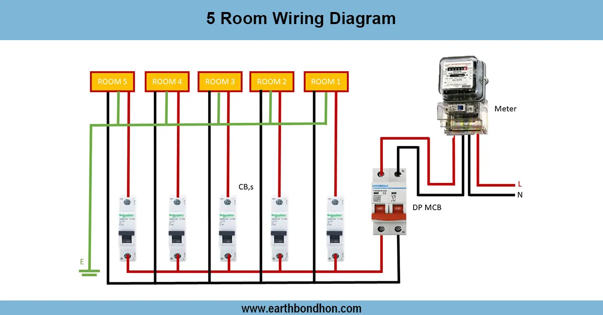
Doorbell Wiring Diagram
Wiring diagram for connecting a doorbell system to 4 rooms. Learn how to use push buttons, bells, and transformers for clear alerts in multiple rooms.
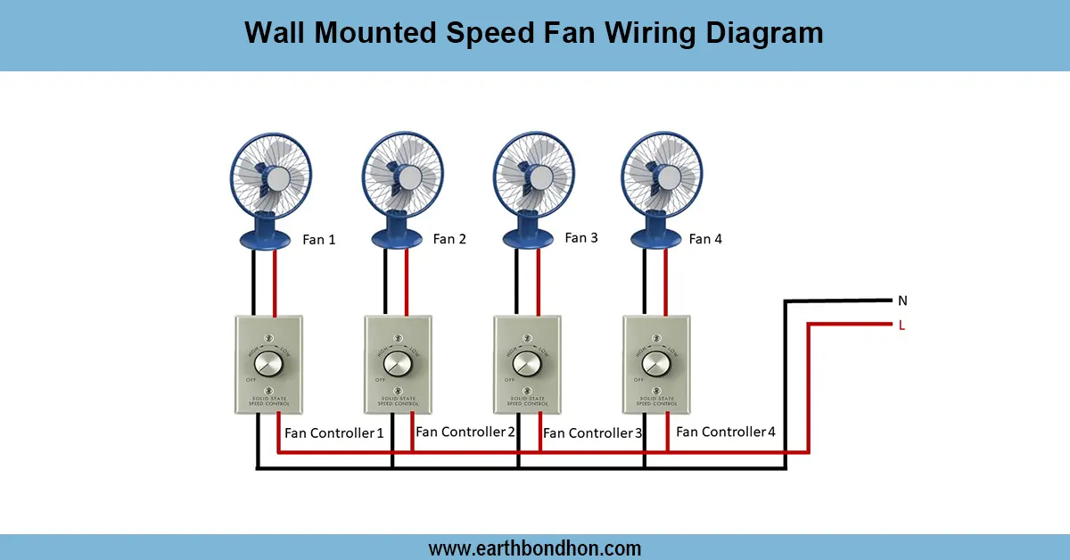
Exhaust fan wiring diagram
Clear wiring diagram and step-by-step guide for wall-mounted speed fans — wiring to switch, speed regulator, capacitor and safety earth for reliable home or commercial installation.
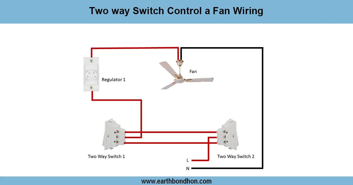
2 way switch control a fan wiring
Easily control your ceiling fan from two different switches using a two-way wiring system. Learn the wiring diagram and connection steps in this guide.
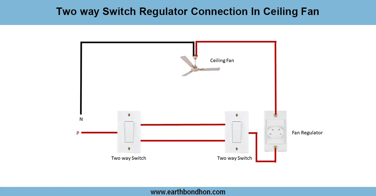
Ceiling Fan Regulator connection
Wiring diagram showing how to connect a two way switch with a regulator to control ceiling fan speed and ON/OFF from two locations.