


Motor with on delay Timer
Wiring diagram for controlling two motors with a single timer to automate motor operation in industrial, agricultural, or manufacturing applications.

two motor one timer wiring
One timer can be used to control two motors electrically connecting the timer output to the contactor coils of both motors so that both motors can be simultaneously started and stopped automatically.
Two Motor One Timer Wiring Summary:
Power Supply: Single or three-phase power to both motors
Timer Output: Feeds both contactor coils
Contactor Coils: One per motor
Protection: Individual overload relays for each motor
Operation: Timer energizes both coils, running both motors together
timer-controlled motor connection
A two motor one-timer wiring is applied in cases where the motors are required to operate simultaneously in starting, stopping and in predetermined schedules. This is achieved by the use of the timer being a control device which energizes both the contactor or relays which are used to drive the two motors. Such an arrangement is frequent with irrigation pumps, conveyor mechanisms, ventilation fans, and meshed up industry processes. The output of the timer is fed to the control coils of two individual distinct contactors and the contactor controls its own motor circuit. Each motor must have its own overload protection by proper wiring with both motors running on the same starting/stopping time. Be sure to match the control voltage of the timer to the coil ratings of the contactors as well as wiring to electrical standards to ensure safe usage.
dual motor control diagram
| Component | Connection | Purpose |
|---|---|---|
| Timer | Control circuit for both contactor coils | Sets motor start/stop schedule |
| Contactor 1 | Controls Motor 1 power circuit | Switches Motor 1 ON/OFF |
| Contactor 2 | Controls Motor 2 power circuit | Switches Motor 2 ON/OFF |
| Overload Relay 1 | In series with Motor 1 | Protects Motor 1 from overcurrent |
| Overload Relay 2 | In series with Motor 2 | Protects Motor 2 from overcurrent |
Frequently Asked Questions - Motor with on delay Timer:
What is a two motor one timer wiring system?
It is a control circuit where one timer operates two motors simultaneously.
Can the motors have different power ratings?
Yes, but each must have its own contactor and overload protection.
Can it work with single phase motors?
Yes, the concept works for both single and three-phase motors.
What type of timer is used?
An electromechanical or digital timer matching control voltage.
Is a separate start button needed?
No, the timer automatically starts/stops the motors.
Can the motors be run independently?
Not in this setup; they run together.
How to protect each motor?
Use individual overload relays and breakers.
Where is this used?
Irrigation, conveyors, ventilation, and synchronized machines.
Can I add a manual override?
Yes, with a bypass switch in the control circuit.
Who should install it?
A qualified electrician familiar with motor control wiring.
Related Posts

4 Gang Switch 4 Bulb Wiring
Learn how to wire a 4-gang switch to control 4 individual bulbs. Ideal for multi-light room setups with simple step-by-step wiring guide and diagram.
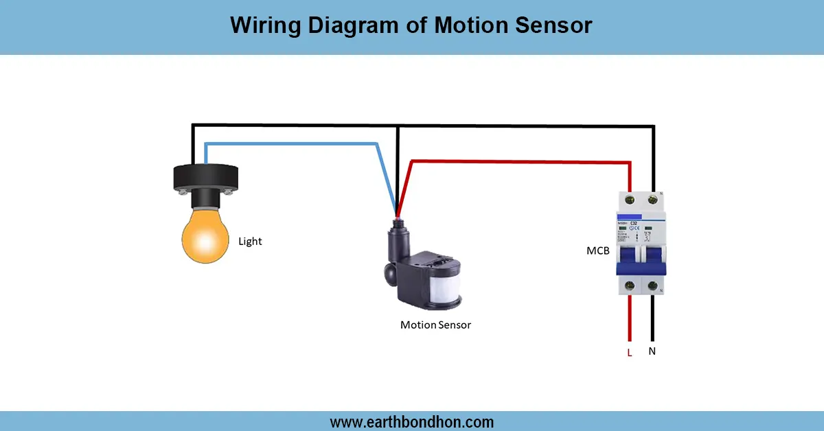
Motion Sensor connection
Step-by-step wiring diagram of a motion sensor connected to a light circuit for automatic ON/OFF control based on detected movement.
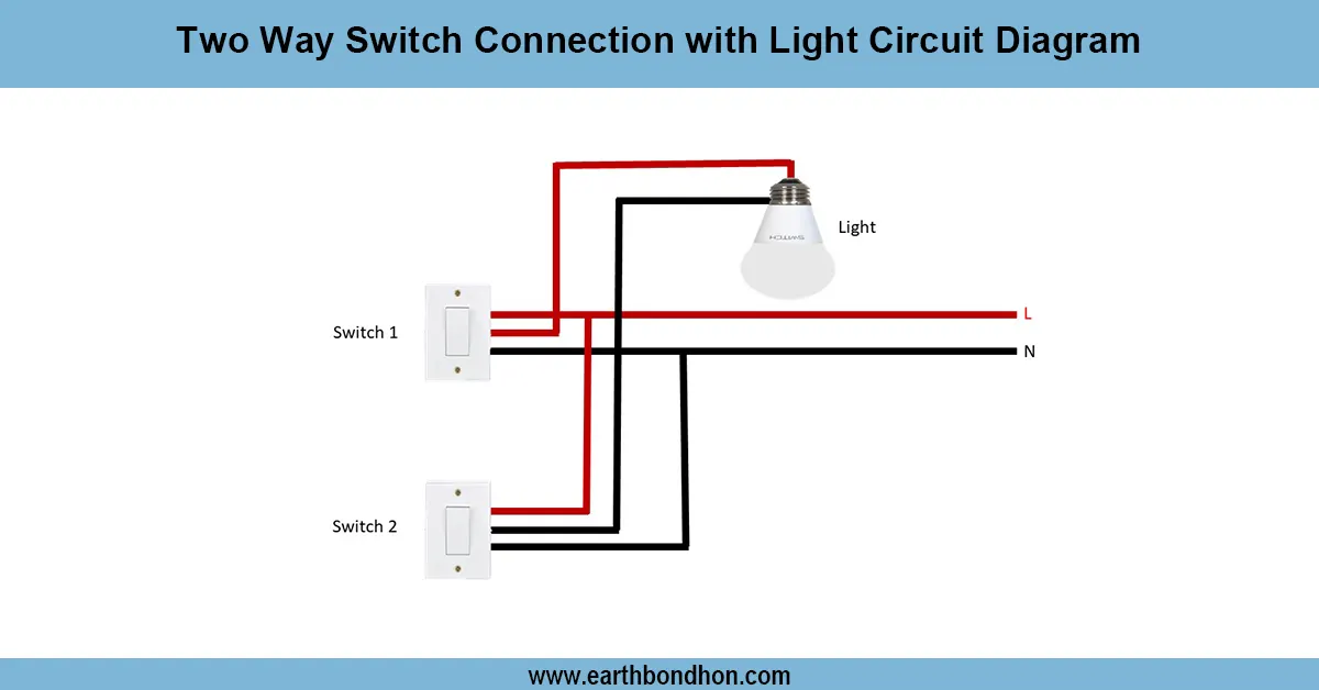
2 Way light switch diagram
Detailed wiring diagram showing two two-way switch connection with a light circuit for controlling a single light from two different locations.
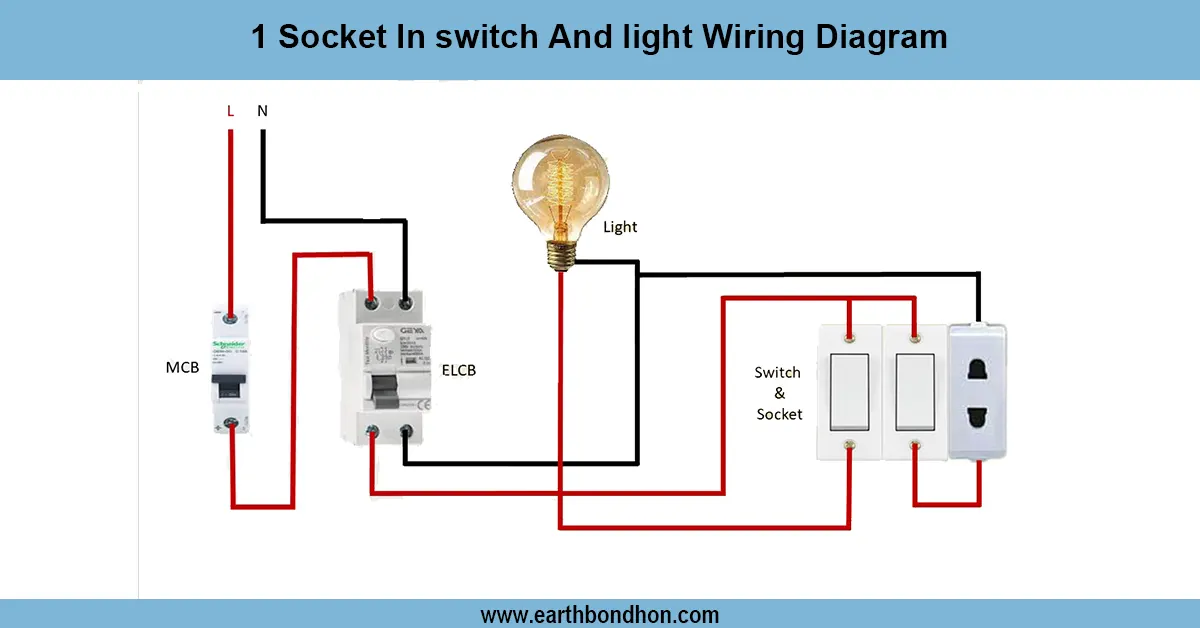
1 Switch 1 Socket connection
Learn how to wire a light and socket using one switch. Simple connection for homes and offices with a clear circuit diagram and safety instructions.
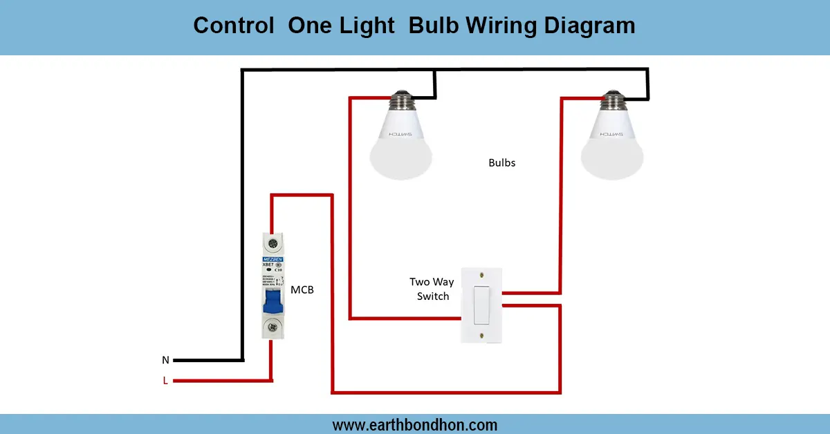
How to Wire a 2 way light switch
Learn how to wire a 2-way light switch to control one light from two locations using simple diagrams and a step-by-step process ideal for home installations.
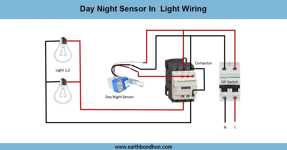
Day Night Light Sensor Switch Circuit
Learn how to wire a day night light sensor switch for automatic lighting control. Save energy and improve convenience with this simple guide and diagram.