


Voltage monitor Relay connection
Learn how to wire a voltage monitor relay in a DOL starter to protect 3-phase motors from phase loss, phase reversal, and voltage faults with easy connection steps.

voltage monitor relay wiring diagram
A voltage monitor relay may be applied in a DOL starter by connecting the three-phase supply to the sensing terminals on the relay, via its NO contact in series with the start button and contactor coil, and the relay output to the overload relay. That is, this provides automatic motor trip upon phase faults.
Formula & Table Summary:
Motor Start Condition: Voltage Healthy + Correct Phase Sequence + Overload NC = Contactor Energized
dol starter control circuit with relay
A voltage monitor relay (phase failure relay) within a DOL starter protects a motor against damage under conditions of phase loss, phase sequence improper, or abnormal voltage. This type of wiring has the relay sense all three phases (l1, l2 and l3) and as such will only enable the contactor to energize when correct conditions are met. Its normally open (NO) output contact has been connected in series with the starter control circuit so that only healthy voltage and phase conditions will cause the motor to start. Provided there is a fault, then the relay will break open the circuit immediately, shutting off the motor and creating no damage. Four -wire connection is a necessitated approach to safety and reliability of industrial 3-phase motors.
motor protection relay connection
| Condition | Relay Output | Motor Status |
|---|---|---|
| All phases OK | Closed | Running |
| Phase loss | Open | Stopped |
| Phase reversal | Open | Stopped |
Frequently Asked Questions - Voltage monitor Relay connection:
What is a voltage monitor relay?
A device that detects phase loss, phase reversal, and voltage faults in 3-phase systems.
Why use a voltage monitor relay in a DOL starter?
To protect motors from electrical faults and prevent damage.
Where is the relay installed?
It is connected in the control circuit of the DOL starter.
Which terminals connect to supply?
L1, L2, and L3 connect to the sensing inputs.
What does the NO contact do?
It closes when voltage and phases are correct, allowing the motor to start.
Does it work with single-phase motors?
No, it is designed for 3-phase systems.
What happens if a phase is lost?
The relay opens the circuit and stops the motor instantly.
Can it detect overvoltage?
Yes, most models can detect both under and over voltage.
Is it adjustable?
Yes, settings for voltage thresholds and delay can be adjusted.
Does it replace overload protection?
No, it works alongside the overload relay for full protection.
Related Posts
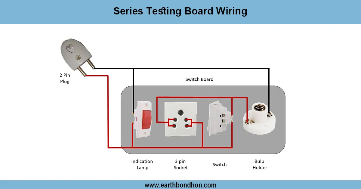
Series Testing Board Connection
Learn how to wire a series testing board with multiple sockets and bulbs. Ideal for electricians and students testing AC appliances or basic electric setups.
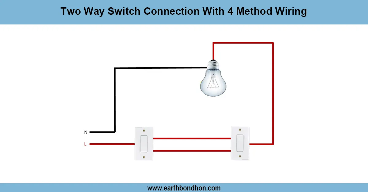
2 Way Light Switch wiring 4 Methode
A 2-way light switch wiring diagram helps control a single light from two different locations. Common in staircases, long hallways, or large rooms.
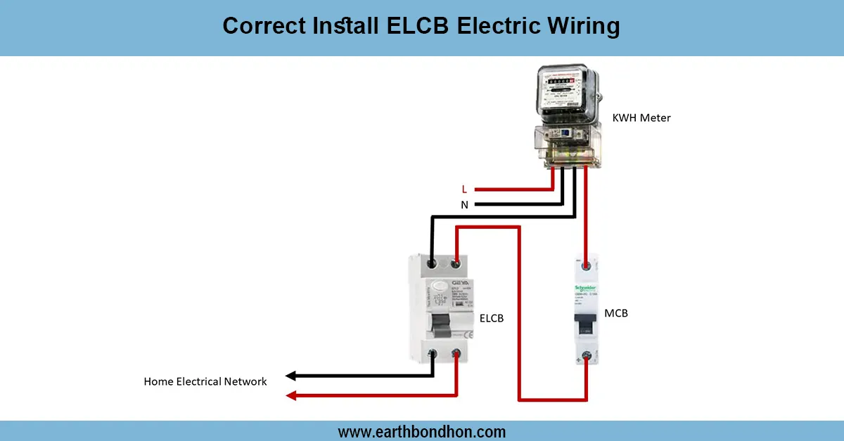
Earth Leakage Circuit Breaker wiring
Learn how to correctly install ELCB wiring to protect against electric shocks and faults. Step-by-step guide for safe electrical wiring with ELCB devices.
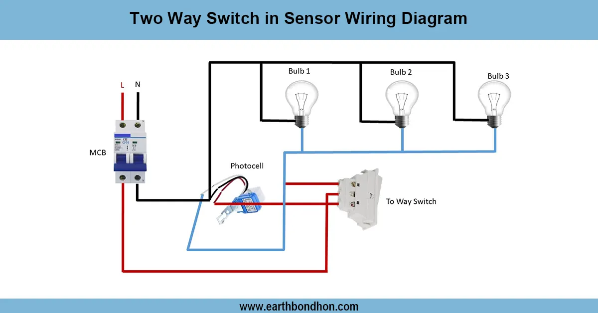
Two way light switch wiring
Wiring diagram showing how to connect a two-way switch with a motion sensor to control a light from two locations with automatic and manual override.

3-Phase ATS circuit wiring
Detailed 3 phase ATS wiring diagram for automatic transfer switch installation to switch power between mains and generator safely and efficiently.
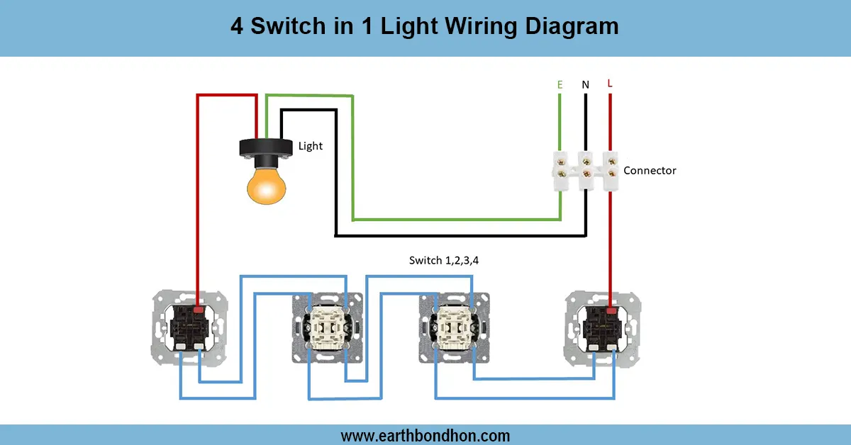
4 Switch 1 Light Control Wiring
A wiring diagram showing how to control one light using four different switches from different locations. Ideal for staircases or long corridors.