

8 Pin Relay In Light Wiring Diagram
Understand how to wire an 8-pin relay for controlling lights using a switch or sensor. Ideal for automation, safety, and efficient lighting systems.

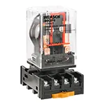
8 pin relay light automation
The high-power circuit of the light can be separated from the control circuit using an 8-pin relay to turn the light on and off using a low-voltage signal like a switch (and even a sensor). It has 2 switching contacts within a relay with increased flexibility as compared to a 5-pin relay. The relay provides a safe and automated means of powering the light because of the way the coil is then connected to a control source, and the Normally Open (NO) contacts are exerted to send power to the light. This can be applied ideally to home automation, street lights, or industrial light systems.
Relay Function Logic:
- Relay Coil (Pin 2 & 7) → Energize via Switch/Sensor
- Common Contact (Pin 1 & 4) → Connected to Load or Phase Line
- Normally Open (Pin 3 & 6) → Connected to Light
- When the coil is energized, NO closes and the light turns ON.
light control using 8 pin relay
An 8-pin relay is typical of automation due to controlling lights, fans, or other loads using low-power switches or sensors. It normally has two changeover(DPDT) contacts, which enable swapping of two circuits. The relay coil gets energized through pin 2 and pin 7, whereby the real load switching occurs through pins 1, 3, 4, 5, 6, and 8. In light wiring it is common to have the NO (normally open) contacts switched to supply power to the light when the relay coil is energized. The arrangement can be applied in applications such as sensor lighting, remote switches, or time-related circuits. Your control signal (e.g., 12V or 24V DC) needs to be the same as the relay coil voltage. The relays are safe to use, and they provide the ability to isolate signals and provide intelligent lighting solutions in which heavy current does not have to be drawn out of infantry switches in a wall.
light control from multiple points
| Pin No | Function | Description |
|---|---|---|
| 2, 7 | Coil | Energizes the relay when powered |
| 1, 4 | Common | Connects to input power or load |
| 3, 6 | NO (Normally Open) | Connects to the load when coil is energized |
| 5, 8 | NC (Normally Closed) | Connects to the load when coil is de-energized |
Frequently Asked Questions - 8 Pin Relay In Light Wiring Diagram:
What is an 8 pin relay?
A relay with 2 coils and 2 changeover switches (DPDT), used for control circuits.
How does an 8 pin relay control a light?
It switches power to the light via NO terminals when the coil is energized.
Which pins are for the coil?
Pins 2 and 7 are for the relay coil.
What voltage is required for the relay coil?
Common coil voltages are 5V, 12V, or 24V DC.
Can I use it with an LED light?
Yes, make sure the relay contact rating supports the LED driver current.
Is the 8-pin relay DPDT?
Yes, it has two sets of changeover contacts.
Where is this used?
Used in automation, alarms, light control, and motor control circuits.
What is the function of NO and NC pins?
NO turns ON when coil is powered; NC is ON when coil is OFF.
Is a relay safer than a switch?
Yes, it provides isolation between control and power circuits.
Can I automate this using Arduino?
Yes, you can control the coil using Arduino's digital output.
Related Posts
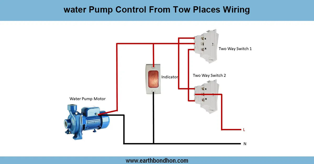
Water pump control from two places
Step-by-step wiring diagram for controlling a water pump from two different locations using two-way switches, ensuring convenience and safety.
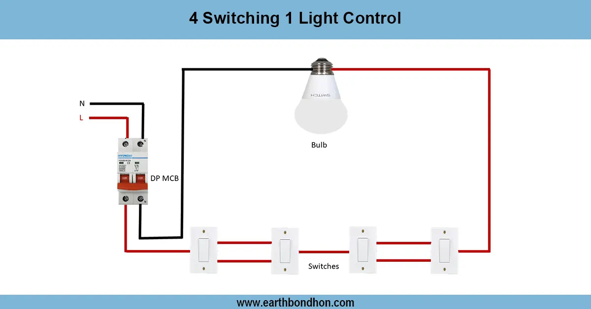
4 Switches 1 Light Control
Learn how to wire 4 switches to control 1 light from multiple locations using intermediate and two-way switches for staircases, hallways, or large rooms.
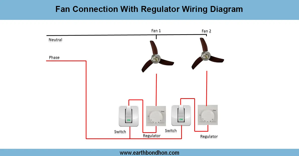
Fan connection with regulator house Wiring Diagram
Learn how to wire a ceiling fan with a regulator at home. Follow this easy wiring diagram and guide for safe and efficient fan installation.
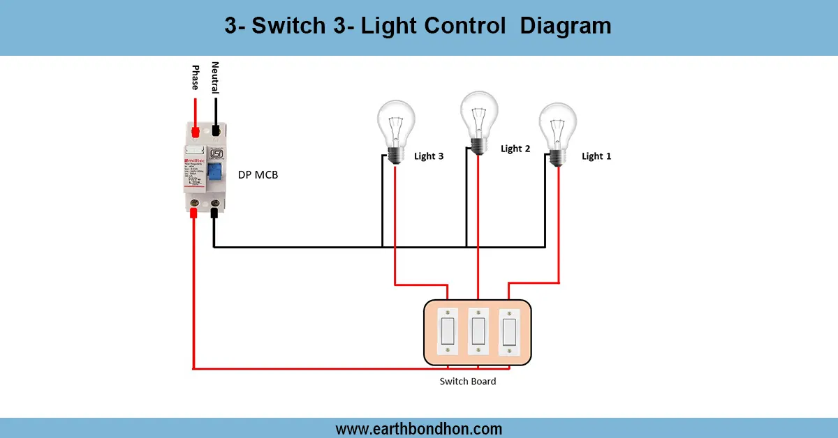
3 Bulbs And 3 Switches Diagram
Learn how to wire 3 lights with 3 individual switches. Easy step-by-step diagram, formula summary, and connection table for beginners and professionals.

Parallel Circuit with 3 bulbs
Understand how to wire a parallel circuit with three light bulbs. Learn the diagram, current flow, voltage sharing, and total resistance with practical wiring tips.
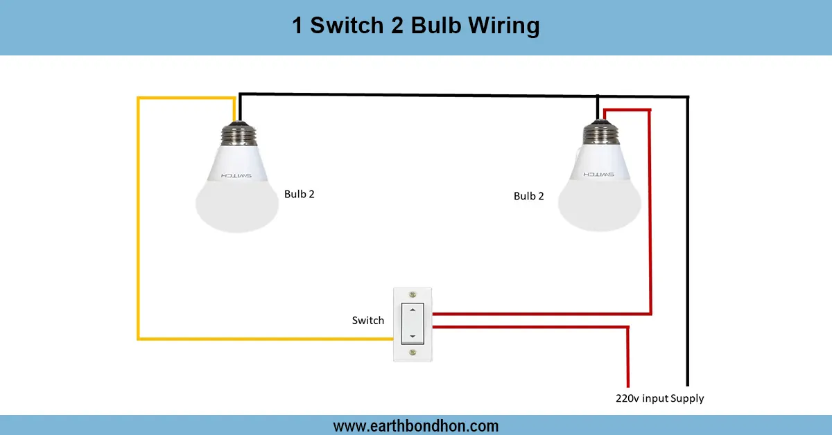
2 Lights 1 Switch Wiring
Learn how to wire 2 lights with 1 switch using a parallel circuit. This guide includes diagrams, FAQs, formulas, and real data to simplify your electrical project.