


3 Bulbs And 3 Switches Diagram
Learn how to wire 3 lights with 3 individual switches. Easy step-by-step diagram, formula summary, and connection table for beginners and professionals.

electrical wiring 3 lights diagram
The process of connecting 3 lights to 3 individual switches is very basic in residential and business electrical setup. The lights have individually dedicated switches so that one can have full control and energy savings. The wiring part is clearly explained by diagrams, simplified formula and illustration of sample input-output table all of which are easy to comprehend, follow and implement by a beginner.
lamp and switch connection Formula Summary
Basic Formula:
Each switch controls its respective light:
3 switch 3 bulb wiring connection
3 Light and 3 Switches Wiring Diagram is a simple construct of electricity with three switches, each controlling one of the three light bulbs respectively. This kind of circuit is widely applied at both residential and schooling places and in small offices. All the switches are in series with the respective bulbs, thus they can be operated separately. It makes fault finding easy, saves energy and maintenance is easy. This arrangement operates on phase-live wires in which they do pass through the switches and common neutral line returns. It would be perfect in situations which individually require control of each light-like a bedroom, hallway or classroom. The guide contains a plain schematic, a table of the input-output connections, and a description of the basic wiring formula to assist an average DIYer and an electrician.
3 light 3 switch wiring diagram
| Switch No | Input (Live) | Output (To Bulb) | Connected Bulb | Output (To Neutral) |
|---|---|---|---|---|
| S1 | 230V | 230V | Bulb 1 (L1) | 0V (Neutral) |
| S2 | 230V | 230V | Bulb 2 (L2) | 0V (Neutral) |
| S3 | 230V | 230V | Bulb 3 (L3) | 0V (Neutral) |
Frequently Asked Questions - 3 Bulbs And 3 Switches Diagram:
How do you wire 3 switches to 3 lights?
Each switch is connected in series with its corresponding light, with the live wire going through the switch and then to the light.
Can each switch control one light separately?
Yes, in this wiring method, each switch independently controls its own light.
Is this suitable for home lighting?
Yes, it’s a common setup in homes for controlling lights in different rooms.
What voltage is used in this diagram?
Typically 230V AC in most residential areas, but it depends on your region.
Is a neutral wire required?
Yes, a neutral line is needed for each bulb to complete the circuit.
Can I use one switch for all 3 lights?
Yes, but that’s a different circuit design. This setup focuses on individual control.
What wire size should be used?
For lights, 1.0–1.5 mm² copper wire is usually sufficient. Always follow local codes.
Is this circuit safe for outdoor lights?
Yes, with proper weatherproofing and protection, it can be used outdoors.
Can I add dimmers to each switch?
Yes, dimmer switches can replace standard ones if compatible with the bulbs.
Do I need a professional electrician?
If you're unsure or not certified, hiring a professional is highly recommended for safety.
Related Posts
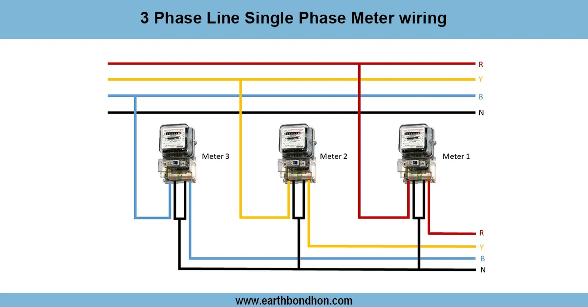
Three-phase to Single Phase Energy Meter
Learn how to wire a single-phase energy meter in a 3-phase line system safely and correctly with a clear wiring diagram and step-by-step instructions.
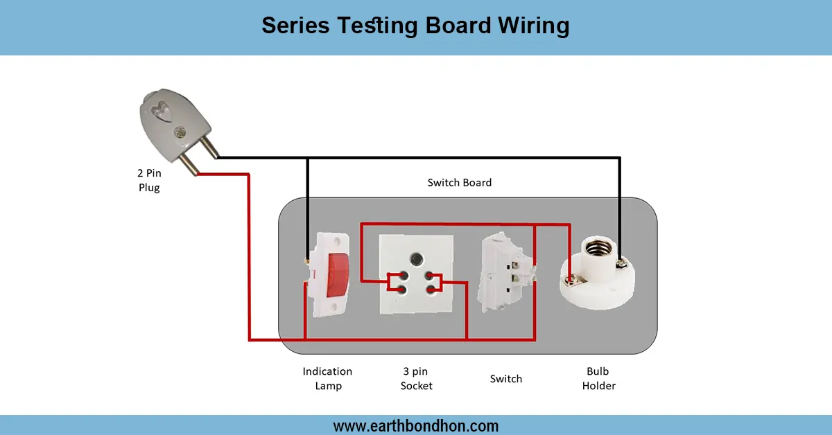
Series Testing Board Connection
Learn how to wire a series testing board with multiple sockets and bulbs. Ideal for electricians and students testing AC appliances or basic electric setups.
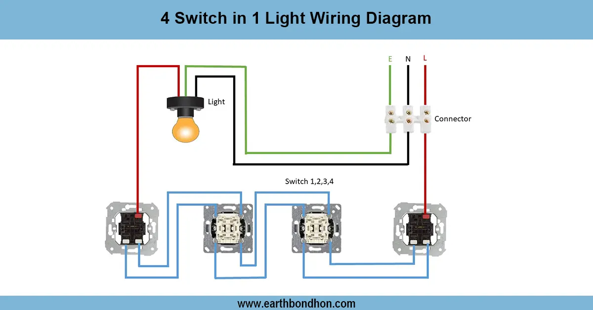
4 Switch 1 Light Control Wiring
A wiring diagram showing how to control one light using four different switches from different locations. Ideal for staircases or long corridors.
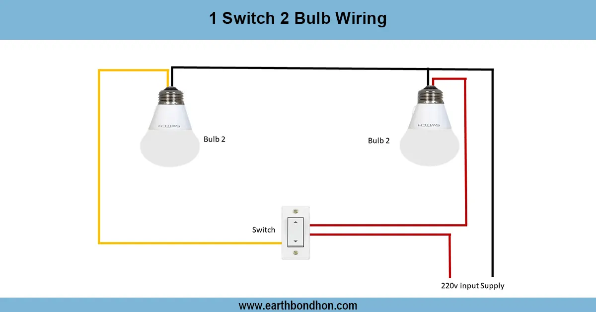
2 Lights 1 Switch Wiring
Learn how to wire 2 lights with 1 switch using a parallel circuit. This guide includes diagrams, FAQs, formulas, and real data to simplify your electrical project.
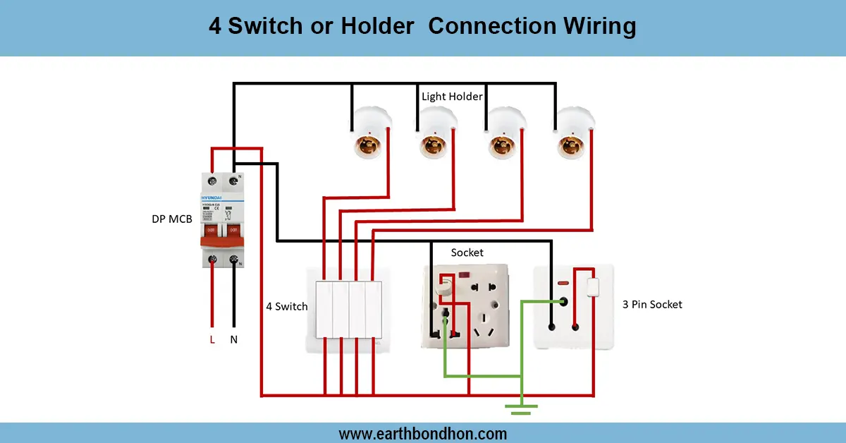
4 Switch Holder Connection Wiring
Learn how to wire four switches to four separate lamp holders for independent control in any room. Step‑by‑step guide with safety tips and cable size recommendations.
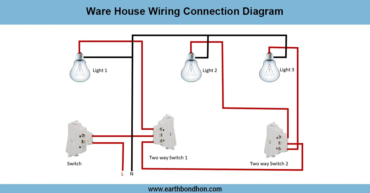
Basic House Wiring
Learn warehouse wiring connection diagrams with clear layouts for lighting, power distribution, and equipment to ensure safety and energy efficiency.