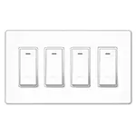


4 Switch Holder Connection Wiring
Learn how to wire four switches to four separate lamp holders for independent control in any room. Step‑by‑step guide with safety tips and cable size recommendations.

switchboard four light wiring
Each switch can switch his/her own light with a 4-switch or a 4-holder wiring system. This is achieved through placing the live wire (phase) to each switch and the switch to the holder. Each of the holders is connected to the neutral directly. This is easy, secure, and convenient for controlling 2 or more points of light in a room or panel. It is commonly used on a domestic switchboard or in a wall panel where individual control is needed.
Wiring Formula Summary:
- Phase wire → Split into 4 → Connects to Switch 1–4
- Switch output → Connects to Holder 1–4 (one each)
- All holders return to a common Neutral line
Total wires: 1 Phase input, 4 switch outputs, 4 neutral lines (can share common neutral bus).
four switch four light circuit
A simple connection wiring circuit setup using 4 switches or holders and 4 connected light holders (bulbs) is independent control of four separate light holders (bulbs) with the use of 4 switches. Every switch is linked easily with its holder in a direct way, and this is isolatingly easy. This format is mostly applied in switchboards where there is a need to have various lights that are operated independently over a number of rooms or areas. Wiring is quite simple: a typical phase line is divided by four switches, each supplying a single bulb, all of which and the neutral go to a single neutral line. This is suitable in the case of a small house, a workshop, or a temporary lighting system.
Independent lamp switch wiring
| Switch | Connected Holder | Phase Connection | Neutral |
|---|---|---|---|
| Switch 1 | Holder 1 | Common Phase → Switch 1 | To Holder 1 |
| Switch 2 | Holder 2 | Common Phase → Switch 2 | To Holder 2 |
| Switch 3 | Holder 3 | Common Phase → Switch 3 | To Holder 3 |
| Switch 4 | Holder 4 | Common Phase → Switch 4 | To Holder 4 |
Frequently Asked Questions - 4 Switch Holder Connection Wiring:
What is a 4 switch 4 holder connection?
It's a wiring setup where four switches independently control four separate light holders.
Can I use one phase line for all four switches?
Yes, you can use a single phase line with separate lines to each switch and holder.
Is this wiring suitable for home use?
Yes, it's commonly used in homes for rooms needing independent lighting.
What type of switches are required?
Standard single-pole switches are typically used.
Do I need neutral wires for each holder?
Yes, all holders must be connected to the neutral line for proper operation.
What is the recommended wire size?
1.5 mm² copper wire is generally recommended for lighting circuits.
Can I use LED bulbs with this setup?
Yes, LED bulbs work well with this type of wiring.
Is this considered a parallel or series circuit?
This is a parallel wiring circuit.
How do I ensure safety in the connection?
Use quality switches, proper insulation, and a circuit breaker for protection.
Can this wiring be done inside a switchboard?
Yes, the switches can be mounted in a switchboard with wires leading to the holders.
Related Posts

3 Phase Motor Star Connection Diagram
Understand the 3-phase motor star connection wiring for motor starting and operation, including wiring steps and benefits of star configuration.
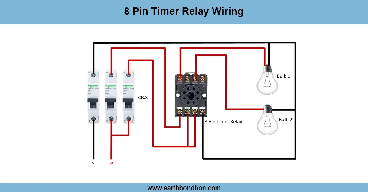
8 Pin Timer Relay Wiring Diagram
Understand 8-pin timer relay wiring with easy diagrams. Learn pinout, connection steps, and functions. Perfect for electricians and electronics hobbyists.

Water level controller wiring
Clear wiring diagram for water level controllers, showing connections to sensors, pumps, power supply, and relays for automatic water level management.
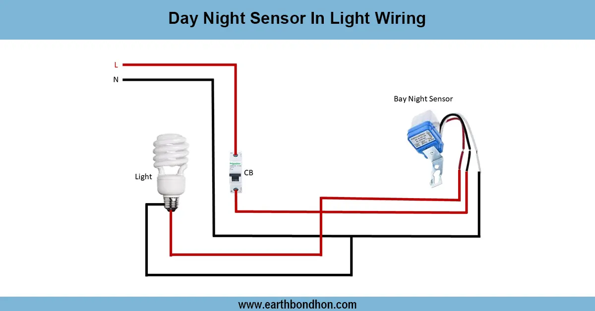
Day Night Sensor In Light Wiring
Wire a dusk-to-dawn (day-night) sensor to automatically control lights at sunset and sunrise. Includes wiring steps, safety tips, and common sensor types.
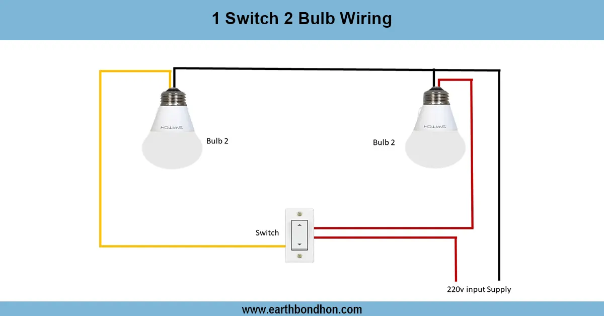
2 Lights 1 Switch Wiring
Learn how to wire 2 lights with 1 switch using a parallel circuit. This guide includes diagrams, FAQs, formulas, and real data to simplify your electrical project.
Series Testing Board Wiring
Learn how to wire a series testing board to safely check appliances, identify faults, and test current flow without damaging electrical equipment.