


Day Night Sensor In Light Wiring
Wire a dusk-to-dawn (day-night) sensor to automatically control lights at sunset and sunrise. Includes wiring steps, safety tips, and common sensor types.

electrical wiring single phase
To install a day-night sensor to wire to automatic lighting, you connect the live wire on your mains to the sensor input, the sensor output to the live terminal on your light, and then all neutrals together. Connections on the ground ought to be firmly fixed. Install the sensor in a place where it gets natural light, but not the direct glare of the controlled source of light, to avoid false switching. This installation will mean your light will be on in the evenings when it becomes dark and off in the mornings when there is light, maximizing convenience as well as consumption of power.
Formula & Table Summary:
Light ON = (Ambient Light < Threshold Lux) → Sensor Output = Live to Load
Light OFF = (Ambient Light ≥ Threshold Lux) → Sensor Output = Open Circuit
Summary Table:
| Condition | Sensor Output | Light Status |
|---|---|---|
| Daylight ≥ Threshold | Open | OFF |
| Nighttime < Threshold | Live Connected | ON |
home electrical wiring single phase
A day-night sensor, also known as a dusk-to-dawn sensor, keeps the lights automatically regulated on the basis of how bright it is. The sensor, once daylight disappears, activates the light, and in the event that the sun emerges, it turns off the light. This is energy-saving, more secure, and eliminates manual operation. The usual way of attaching the wires is to attach the sensor in series with the live supply side of the switch to the light fitting, again taking care to ground well and have the correct polarity. The vast majority of the sensors will need the presence of a neutral connection, though simpler sensor usage has the wires. You must also keep it well-positioned to avoid false triggering- place the sensor in an area where it has a clear view of the sky yet uninterrupted by direct artificial light. The arrangement is appropriate for both LED, CFL, and incandescent lights, provided the compatibility of the specifications of sensor. Never go against the wiring instructions that the manufacturer provides, and ensure observance of electrical safety standards. In case of doubt, employ the services of a licensed electrician to be safe regarding local regulations.
single phase wiring diagram
| Lux Level | Sensor Output | Light State |
|---|---|---|
| 800 Lux | Open | OFF |
| 300 Lux | Live to Load | ON |
| 100 Lux | Live to Load | ON |
Frequently Asked Questions - Day Night Sensor In Light Wiring:
What is a day-night sensor?
A sensor (photocell or LDR) that detects ambient light and switches lights on at dusk and off at dawn.
Where do you install the sensor?
Outside or in a location with clear sky exposure, away from direct lamp light to avoid false triggering.
How do I wire a dusk-to-dawn sensor to a light?
Connect mains Live to sensor input, sensor output to fixture Live, and join neutrals; ensure proper earth/grounding.
Do I need a neutral at the sensor?
Some sensors are two-wire (no neutral) but many modern sensors require neutral — check the model spec.
Can I use it with LED lights?
Yes, but choose a sensor and driver compatible with low current/LED inrush characteristics.
Is polarity important when wiring?
Yes — connect Live, Neutral and Earth correctly and follow the sensor’s labeled terminals.
Do sensors need surge protection?
Recommended for outdoor installations to protect against lightning or switching transients.
Can I dim lights with a day-night sensor?
Typical photocells are on/off devices; for dimming you need a sensor + dimmable driver and compatible control circuitry.
How do I prevent false triggers?
Mount sensor away from stray light, reflective surfaces, and position to face the open sky.
Is professional installation required?
If you are not confident working with mains electricity, hire a licensed electrician for safety and code compliance.
Related Posts
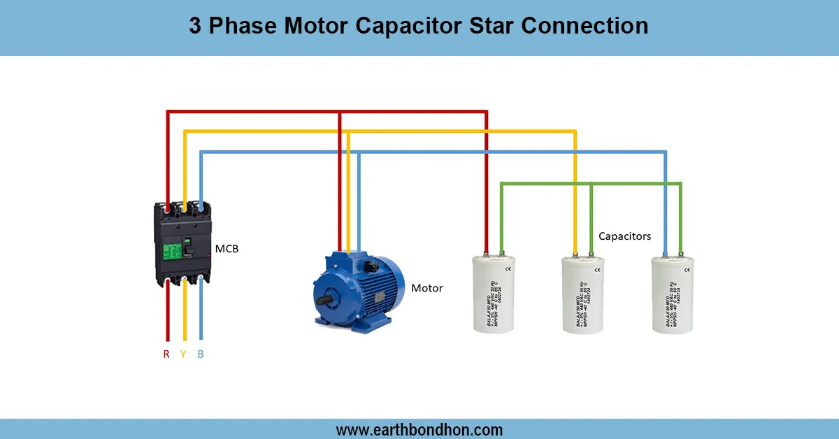
3 Phase Motor Star Connection Diagram
Learn 3-phase motor capacitor star connection wiring for starting and running capacitors, ensuring efficient motor operation with clear wiring steps.
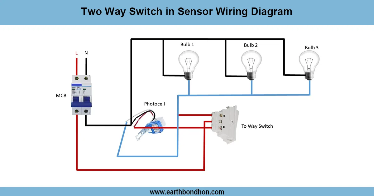
Two way light switch wiring
Wiring diagram showing how to connect a two-way switch with a motion sensor to control a light from two locations with automatic and manual override.
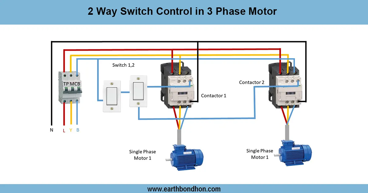
2-way Switch Control in 3-Phase Motor
Learn how to use a 2-way switch control for a 3-phase motor to operate it from two locations, including wiring diagrams and safety tips for reliable control.

Manual Light sensor connection for street light
Wiring diagram for 3-phase electric systems using light sensors to automate lighting control, improving energy efficiency and safety in industrial and commercial setups.
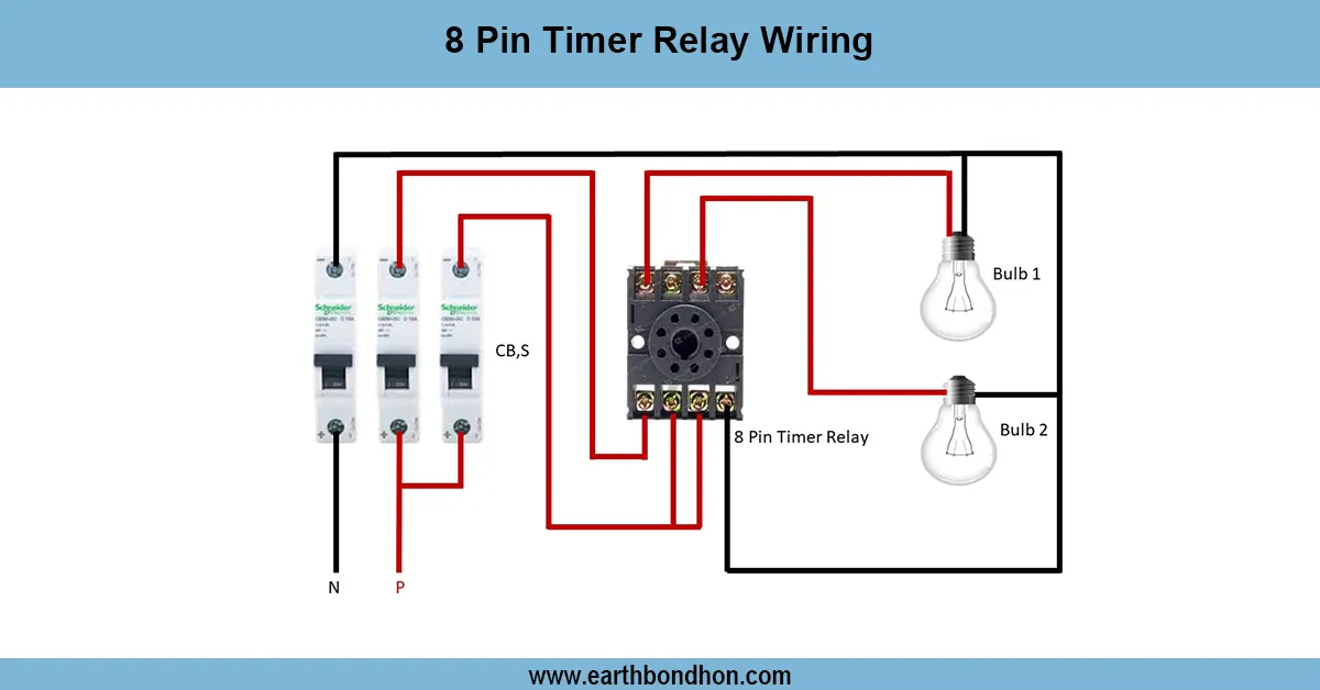
8 Pin timer Relay wiring
Learn the pin configuration and wiring method for an 8‑pin timer relay to control loads with delay. Includes coil connections, NO/NC contacts, and timing logic.
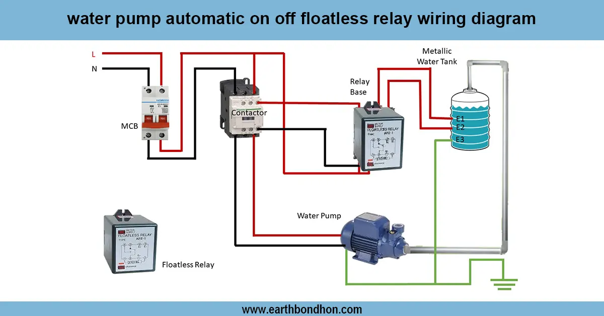
Automatic water level controller wiring
Clear wiring diagram and guide for water pump automatic ON/OFF using a floatless relay, ensuring reliable pump control without mechanical floats.