


8 Pin timer Relay wiring
Learn the pin configuration and wiring method for an 8‑pin timer relay to control loads with delay. Includes coil connections, NO/NC contacts, and timing logic.

8 pin timer relay wiring
Learn the pin configuration and wiring method for an 8‑pin timer relay to control loads with a delay. Includes coil connections, NO/NC contacts, and timing logic.
Wiring Formula Summary:
Relay Coil Voltage: V = IR (Use Ohm’s Law to check relay current requirement)
Delay Function: Depends on timer module — ON Delay or OFF Delay logic.
- Pin 2 & 7: Coil connections
- Pin 1: COM 1 → Pin 3 NO, Pin 4 NC
- Pin 8: COM 2 → Pin 6 NO, Pin 5 NC
timer relay wiring diagram
An 8‑pin timer relay is used to control electrical loads with a preset delay using a DPDT contact arrangement. It provides both normally open and normally closed outputs across two separate channels. Understanding its pin configuration helps ensure safe and efficient circuit wiring for motors, lamps, and automation systems.
8 pin timer connection
| Pin | Function | Type | Notes |
|---|---|---|---|
| 2, 7 | Coil | Power Input | Apply voltage to activate timer |
| 1 | COM 1 | Contact | Switches between NC (4) & NO (3) |
| 8 | COM 2 | Contact | Switches between NC (5) & NO (6) |
Frequently Asked Questions - 8 Pin timer Relay wiring:
What is an 8‑pin timer relay?
A timer relay with coil, two common contacts each with NC and NO terminals.
Which pins are for the coil?
Pins 2 and 7 are used for the coil (L and N supply) on most models.
How are relay contacts arranged?
Pins 1 & 8 are COM; 1 NC‑4/NO‑3; 8 NC‑5/NO‑6 contacts.
Which pins are NO and NC?
Pin 3 & 6 are NO; pin 4 & 5 are NC relays.
Can the timer drive motors?
Yes, in auto ON/OFF circuits for motors using appropriate rating.
Is this a DPDT timer?
Yes, two separate poles each with NC/NO outputs.
What voltage is coil rated?
Common options: 12 VDC, 24 VDC, 110 VAC, or 220 VAC depending on model.
Can I wire it without a diagram?
It’s risky; pin numbering and logic vary—always follow manufacturer pinout.
Do I need MCB protection?
Yes—use a SP or DP MCB/RCCB rated for coil and load currents.
How do I use it for delay ON/OFF?
Apply coil voltage to start delay, contacts change after set duration.
Related Posts
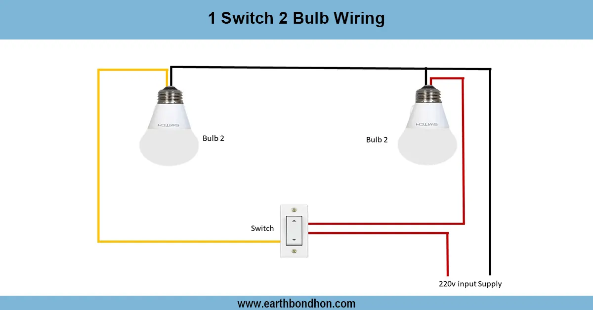
2 Lights 1 Switch Wiring
Learn how to wire 2 lights with 1 switch using a parallel circuit. This guide includes diagrams, FAQs, formulas, and real data to simplify your electrical project.

3-phase distribution Board wiring circuit
Complete wiring diagram for 3 phase distribution board with MCCB, showing connections for incoming supply, breakers, and load distribution for safe power control.

3-Phase ATS circuit wiring
Detailed 3 phase ATS wiring diagram for automatic transfer switch installation to switch power between mains and generator safely and efficiently.
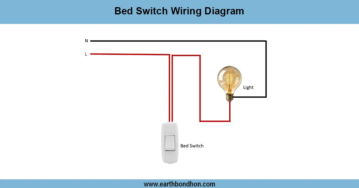
Bed switch connection wiring
Understand bed switch wiring with step-by-step diagrams, easy connection instructions, and common FAQs for safe bedroom lighting control.
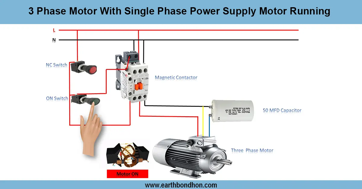
3 Phase Motor in Single Phase Connection
Learn how to run a 3-phase motor on a single-phase power supply using capacitor start or phase converter methods for reliable motor operation.
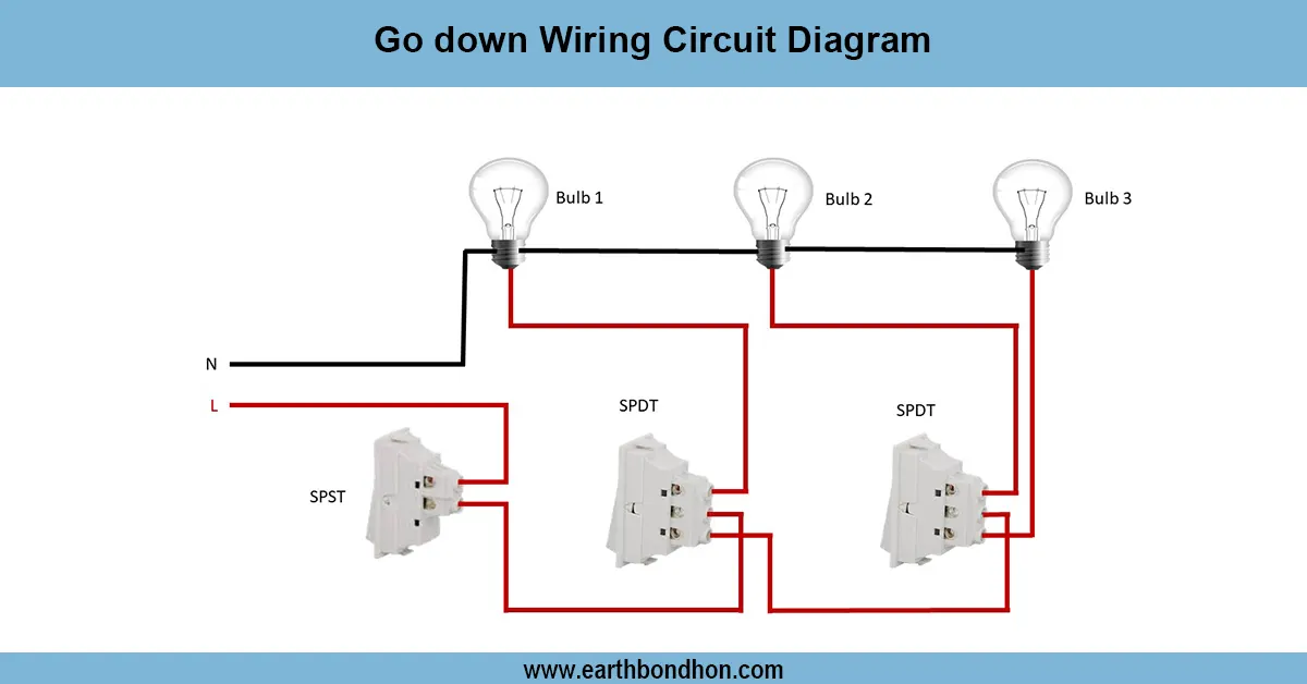
Go down Wiring Circuit Diagram
Learn the Go Down wiring circuit diagram with clear steps for safe, efficient electrical wiring. Perfect for warehouses and storage areas.