


One Light one Switch Connection
Learn how to wire a single light with a single switch. Ideal for basic electrical setups in rooms, bathrooms, and small utility areas.

light switch diagram
A one-light, one-switch wiring connection is the most basic electrical circuit in which one switch and one light are involved. Such a simple installation is typical in residential areas and small rooms. It entails connecting the phase wire to one terminal of the switch and then to the other, the phase input of the light. The other side of the light is attached to the neutral wire. To a novice this circuit is ideal, and it makes a good example to illustrate how current flows around an easy electrical wiring.
Formula & Table Summary:
Connection Formula:Light = (Phase → Switch → Light) + (Neutral → Light)
Working Principle: Current flows only when the switch is ON, completing the circuit.
single pole switch circuit
One light and one switch is the most fundamental and the standard type of wiring. It provides individual light switch control over the given light bulb. The phase (live) wire will have a path via the switch and then to the light, and the neutral leads directly to the light. On turning the switch ON, the circuit is complete and the light is lit. This is a perfect arrangement when basic lighting requirements are the requirement in the rooms, bathrooms, and small spaces where a single light fixture suffices. It is also free and easy to use, can be installed easily, and is affordable for residential and small use.
Room light switch connection
| Switch State | Light Status | Current Flow | Circuit Condition |
|---|---|---|---|
| ON | Light ON | Flowing | Complete |
| OFF | Light OFF | No Flow | Open |
Frequently Asked Questions - One Light one Switch Connection:
What is a one light one switch connection?
It is a basic electrical circuit where one switch controls one light bulb directly.
Where is this type of wiring used?
Commonly used in rooms, bathrooms, and areas requiring only one light fixture.
How does the circuit work?
The switch controls the flow of current to the light; turning ON completes the circuit.
Which wire goes to the switch?
The live (phase) wire is routed through the switch to the light.
Does the neutral wire go through the switch?
No, the neutral wire is connected directly to the light fitting.
Is this setup safe for beginners?
Yes, it's one of the safest and simplest circuits to learn for beginners.
Can I use LED bulbs in this circuit?
Yes, LED bulbs work perfectly in one switch one light circuits.
What tools are needed for installation?
You need a screwdriver, wire stripper, tester, and electrical tape.
How many wires are needed?
At least two wires: one for phase through switch, one for neutral to the light.
What if the switch doesn't turn the light on?
Check wiring continuity, switch terminals, and bulb functionality.
Related Posts
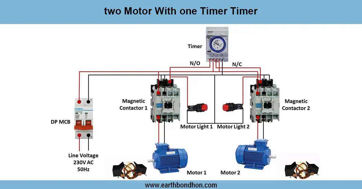
Motor with on delay Timer
Wiring diagram for controlling two motors with a single timer to automate motor operation in industrial, agricultural, or manufacturing applications.

3 Phase SPD Connection
Detailed 3 phase SPD connection diagram showing how to wire surge protection devices to safeguard electrical systems from transient overvoltages.
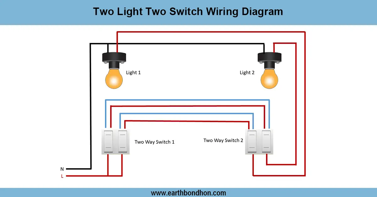
1 Light controlled by 2 switches
Control one light using two switches located at different positions with a simple two-way switch wiring setup. Ideal for hallways, staircases, and bedrooms.
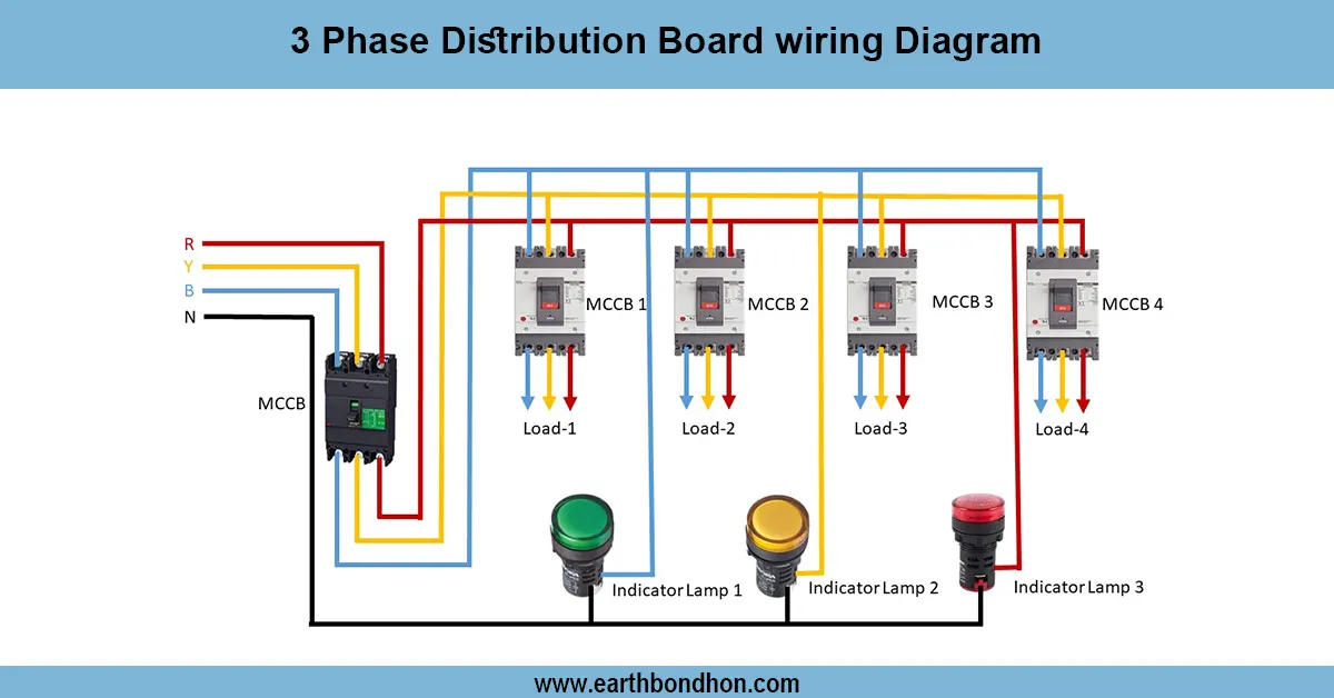
3 Phase Distribution Board wiring
Comprehensive 3-phase distribution board wiring guide for safe and efficient power distribution with MCCB, breakers, neutral, and earth connections.

Voltage monitor Relay connection
Learn how to wire a voltage monitor relay in a DOL starter to protect 3-phase motors from phase loss, phase reversal, and voltage faults with easy connection steps.
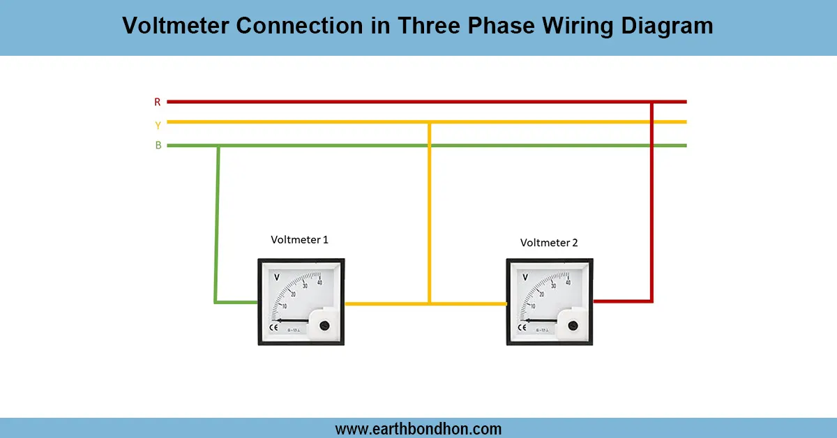
Three phase voltmeter connection
volts times the square root of 3, which happens to be rounded off to 1.732. For 2 lines each carrying 120 volts, the calculation for this is 120 volts times 1.732, and the result is rounded up to 208 volts.